The electric furnace is three-phase. Power outlet for electric stove: types, device, technical norms, connection rules
Those who decided to save money or simply have the appropriate experience, can proceed to the independent connection of the electric cooker, but for this you must follow certain rules.
Safety regulations
It is important to pay increased attention to reliability by connecting the electric stove with your own hands. Therefore, a correctly performed connection is a guarantee of security. Before you begin the process of connecting the slab you should read the instructions. Do not forget that a mistake in making a connection can cause a breakdown of the electrical device at best, and at worst - lead to an ignition postings and the occurrence of a fire. If you have not previously encountered such works, it is necessary to charge them with a qualified electrician for their own safety.
Preparatory work
- It does not matter what kind of actions are performed with electrical network, it must necessarily be previously disabled.
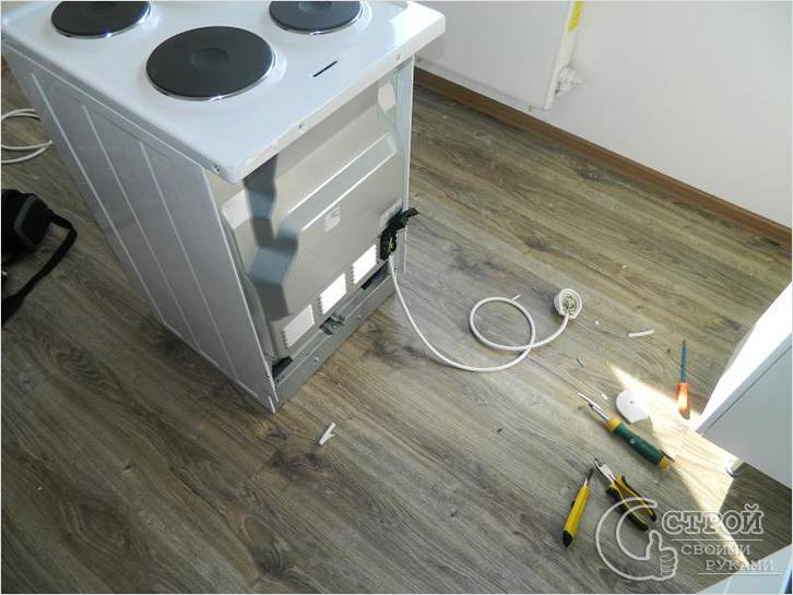
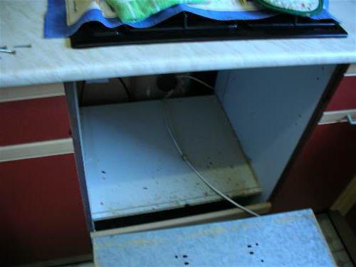
- The electric plate must be removed from the package and visually inspected for damage and assembly.
- Next, turn off the old tile and remove it.
- Having studied the instruction and following its recommendations, determine the optimal location for new home appliances.
As a rule, slabs of modern production do not include a connecting cord when selling. This is due to the fact that the devices are preferably connected using terminal blocks. Using such a connection, we can replace the automaton fuse-links and connect the plate with the source of electricity with the help of longer wires. The socket is only permissible if it is capable of withstanding a current strength of more than 32 amperes. In no case can the appliance be connected to an ordinary outlet, as it consumes a large amount of current that can not stand the standard power grid. To do this, you need to bring a special cable and install a separate machine. It is forbidden to connect the device through a "bug".
Instruction for connection to a single-phase line
For correct connection, the order of actions should be as follows:
- Disconnect the machine responsible for feeding the single-phase line;
- The power cable must not be more than 2 meters - this will allow the plate to be moved if necessary;
- Then make sure that the cable is selected correctly and has the required cross-section and fuse, and then open the plug of the power supply unit of the appliance;
- Plates can be connected to three or single-phase power supply (in the apartments the second option);
- In the gap between the terminals, bridges of copper, having a section of 6 square meters, are installed. mm, which are supplied with the stove;
- Next, the phase, ground and neutral conductors must be connected to the terminals. Ensure the bolted connection of the terminals is secure, otherwise it may cause a fire;
- The phase is determined by the indicator, zero - probe;
- On the wire of the plate a fork is fixed, under which the three-pin power socket is mounted;
- After inserting the plug into the socket, it is necessary to make sure that there is no grounding with a tester;
- Then check the presence of short circuits between zero and phase in all modes of operation of the device, with sufficient indicators of the tester, you can start the machine;
- With no socket connection, the connection of the conductors is carried out in a terminal box fixed to the wall surface with screws at a distance of 60 cm from the floor;
- Check the device for operation: check each cooking zone separately, and also set the oven to light;
- At full serviceability it is possible to start operation.
Connection to a three-phase line
When connecting an electric stove in a rural private house a three-phase connection can be used, the order of the actions will be slightly different:
In order for the home appliance to work properly, it is necessary to equip it with a protective earth. To do this, make sure that the electrical housing housing is also grounded. In case of grounding, you can connect the ground conductor to the housing. Never use as a earthing connection with communicative pipes.
The plate must be installed in such a way that there is no possibility of contact between the housing and the components without voltage.
This almost ends the process of installing the electric stove. In the event that you are not sure of your abilities, you should seek help from specialists, rather than risk your safety and the safety of your loved ones.
Video
The following video will tell you how to properly install and connect an electric stove:
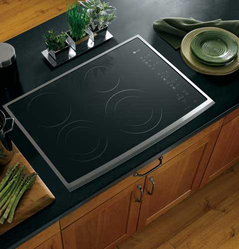
Today, in the world of electric cookers, glass-ceramic electric cookers, plates with induction heating and conventional electric cookers are produced. The connection of the electric stove is not different for all the plates and it is easy for many, without knowledge in the electrician. Electric plates can be connected to single-phase or three-phase networks.
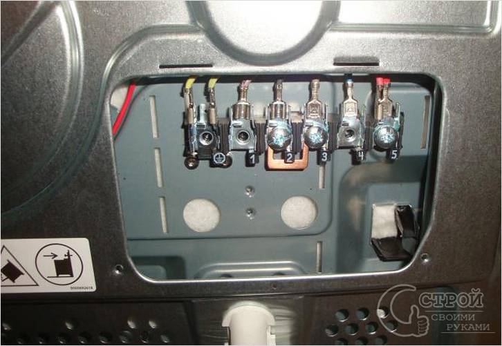
Type of terminal block for connecting the electric cooker
With a plate thickness of up to 3 kW, connect it through a fuse 13A and a plug with a socket also rated at 13A. If the capacity of the electric stove is above 3 kW, then it is connected through a separate cable from the input electrical board.
Correct connection of the electric stove with your own hands
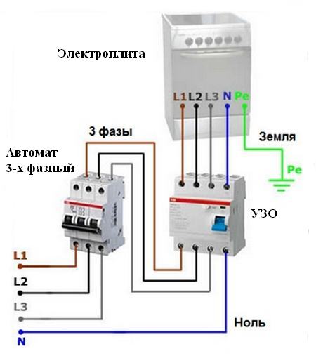
Before connecting, conduct a 3-core cable with a cross-section of 6 mm² from access control panel up to the apartment board. For a single-phase network in an apartment panel, the introductory machine should be set at 40A. Another separate machine on the plate is put on 32A.
Next to the machine in the switchboard, a protective shutdown device is installed at 32A with a 30 mA tripping current. With a three-phase network put circuit breaker 3-pole and 16A current, a 4-pole three-phase RCD at 25A and a 30mA tripping current are installed side by side.
Wiring diagram for connecting an electric cooker to a three-phase network
Which cable and outlet for connecting the electric stove?
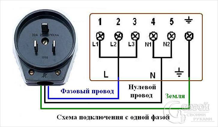
In the case of a single-phase network, a socket with a plug is taken at 32A with three contacts - this is the phase, zero and protective earth. If the connection needs to be made to a three-phase network, then use a 5-pin socket with a plug, designed to connect phases L1, L2, L3, zero and protective earth.
For a single-phase network, the cables are supplied with BBG grades - 3x6 - 3-core, copper-6 mm². In the absence of an electric pad on the electric stove, the cable is connected by soldering or by pressing. For a three-phase network, the cross-section of copper conductors of the cable is 2.5 mm² or more.
If the capacity of the electric stove is above 3 kW, the cable is installed through the cable channel from the apartment board to the electrical outlet. Use this cable for other purposes is prohibited. The rules for conducting electrical wiring in wooden house are different.
Options for connecting the electric stove with your own hands
When connecting the power cable for an electric stove, it is necessary to observe the correct color marking of cores . For the neutral wire, blue, or shades of blue, are used, the yellow-green color of the wire is used to mark the protective earth PE. The phase wires can be painted in white, brown, black, as well as in red, gray and other colors.
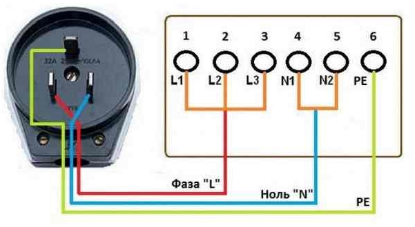
Connecting an electric stove in a single-phase network
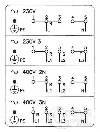
With this connection, all terminals marked L1, L2, L3 on the power supply board of the electric stove are short-circuited, i.e. a jumper is placed copper wire 6 mm².
Scheme of connecting an electric stove to a single-phase network
Terminals N1 and N2 are also short-circuited by a jumper and connected to the wire N, the PE terminal is connected to the protective ground. The PE terminal is always installed on the appliance body.
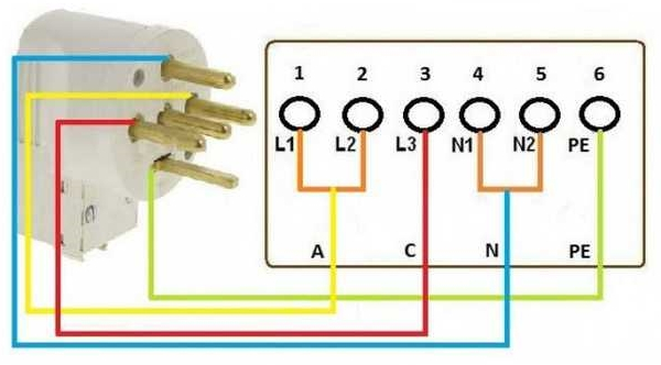
Electric stoves can be connected in 2 phases
According to the 2-phase scheme, the connection is made according to the scheme. Between the two phases L1, L2 screw the jumper and connect the phase conductor A, the terminal L3 connect phase C.
Scheme of connecting an electric stove to a two-phase network
Terminals N1, N2 are short-circuited by a jumper, the terminal marked PE is connected to the protective earth (yellow-green wire).
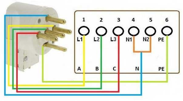
Connection of 3-phase network to the plate
In a three-phase network, phases A, B, C are connected to terminals L1, L2, L3. It is not necessary to look for the correct phase sequence here, phases can be connected in any sequence. The electric stoves can be connected in the electrical systems of systems with common protective grounding TN-S and with separate protective grounding TN-C-S.
Scheme of connecting an electric stove to a three-phase network
If there is no such grounding, then it must be made and output to the PE terminal of the apartment or house electric switchboard. Similar electrical devices as an oven, various in the design of cooking hobs and varieties of electric cookers, is connected in the same way. For different power of electrical appliances, its cable cross-section is calculated.
Acquiring a new electrical appliance, first of all, it should be evaluated from the standpoint of reliability, economy, design possibilities, in order to choose the model that with the greatest benefit, for a long time morally not aging, will satisfy your requirements.
But no matter how carefully you choose an electrical assistant, sooner or later it will fail. Do not rush, however, throw out the faulty electrical appliance. Firstly, not always in the store there is a replacement, and secondly, the breakdown may not be very difficult and you will be able to fix it yourself. First of all, you should determine the cause of the breakdown.
The defective element in the faulty device can be detected by the external manifestations of the device (for example, overheating of the motor winding in the fan, insufficient heating of the plate of the electric plate), by inspection (weakening of the contact clip, wear of the engine collector in the vacuum cleaner, etc.) and, finally, electrical measurements (breakdown of insulation between the current-carrying element and the body of the device, breakage in the power cord, etc.). In most cases, it is advisable to combine these search methods, beginning with the elucidation of possible causes of malfunction and external inspection.
Not all the defects that have arisen immediately "signal" about themselves as an external manifestation. Such defects (wear of collector brushes, a crack in the rubber tube inside the body of the washing machine, clogging up the lubrication of bearings, etc.), if not detected in time, will eventually lead to a breakdown, which can always be eliminated even under the conditions of a repair shop . Identify such defects can be with a preventive examination of the device. Therefore, for any most simple repair, requiring the opening of the body of the device, it will always be justified to inspect all of its elements and check the contact connections. Prophylaxis is a real extension of the life of the device. This is also facilitated by a "sparing" mode of operation (reducing the load, reducing the time of continuous operation, in some cases - reducing the supply voltage, etc.).
Electric tiles. The rated output of the single-burner electric hot plates produced by the industry is 800, 1000, 1200 and 1500 W, two-ring power plants - 1600, 1800, 2000 and 2200 W. According to the design, there are three types of burners: with a body stamped from sheet steel, with a cast iron casing, with tubular electric heaters (TEN).
The type of the burner, the power control device are the main elements that determine the performance characteristics of the hotplates. The time for heating the burners with heating elements 3-4 minutes, their efficiency is 70%, the surface heating temperature is 650-700 ° С, the average life is 5 thousand hours. The corresponding characteristics of the stamped burners: 15 minutes; 55%; 450-500 ° C, 2-3 thousand hours. The characteristics of cast iron burners occupy intermediate values. The most perfect are the tiles with heating elements. The heating surface of the heater is a tube of thin metal, due to which it heats very quickly, and the heat transfer occurs mainly as a result of radiation. In addition, heating elements (unlike cast iron burners) do not crack when water hits their hot surface. TENs in electric stoves are used with double-end single-spiral pipes with a tube diameter of 7.4-10 mm and single-end double-helix with a diameter of 16 mm. The design of the most common burners is shown in Fig. 23.
Fig. 23. Electric hotplates: a - cast iron; b - with a two-terminal TEN; в - with two two-terminal ТЭНами; g - with one-terminal TEN
To ensure rational heating, power controllers are built into the tiles. The circuit for switching the helixes of a double-helical burner with a four-position cam-operated switch is shown in Fig. 24. In electric cookers with electric heaters, infinitely variable power regulation is usually used. The power is regulated within 15-100% of the nominal value.
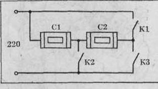
Fig. 24. Diagram of switching the spirals of the burner: C1 and C2 - spirals;
К1, К2, КЗ - switch contacts
If the tile does not heat up when plugged in (not working), the cause may be a malfunction of any element in its electrical circuit - the power cord, the burner spiral, the regulator contacts or the power switch. The principle of troubleshooting in an electric hotplate will be considered more thoroughly, in order to use it as an example when repairing other devices that have mode switches. As an example, we choose an electric stove with a double-helix burner and a four-position power switch, and we begin by looking at the effect of possible malfunctions on the appearance of tile elements.
A burning indicator lamp relieves suspicion of a break in the power cord. If it does not burn, it is most likely a break in the cord, usually at the plug or at the exit from the device body, that is, in the places most often bent. If the light is on (the cord is working), you will have to check other circuit elements. In the absence of a circuit, it is easy to compose, following the installation chains in the hob body. The order of switching on contacts is determined by observing their position at each switch position (the observational data is given in Table 5).
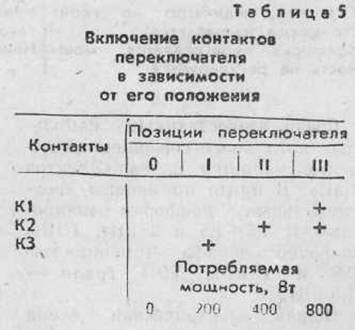
Based on the general scheme and the contact inclusion table, we estimate the effect of each element on each switch position on the operating mode of the burner. The burner will not heat up: at the position of the switch I when the coils C1 and C2 break off or the contact of the short-circuit switch is broken; at position II with a break in the helix C1 or a violation of the contact K2. At position ІІІ at breakage of spirals С1 or С2 or violation of contact К1, the burner will be heated with a power equal to half the maximum. The effect of each defective element on the heating mode of the burner is summarized in Table. 6, which will allow us to solve the inverse problem - to determine the faulty element by the heating mode of the burner at different positions of the switch.
At each switch position, from each defective element, a set of hotplate heating modes specific for this fault will appear. For example, if the burner heats only at switch I (see column 5 of Table 6), the cause of the fault is contact K2. Only it completely breaks the power supply circuit of the burner both at switch II position and position III. Another example: the burner heats up only at switch III and only at half power (see column 2 of Table 6). Cause: an open in the circuit of the spiral C1 (only element C1 breaks the circuit completely at positions I and II, and the half-power mode at position III additionally confirms the cause).
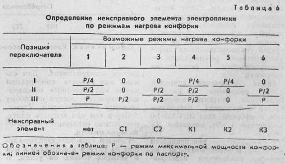
So, we learned without any special devices Identify faulty items depending on their effects on different switch positions.
If home master is puzzled only by the restoration of a faulty device without the desire to use each case for experience accumulation, it can find a malfunction in an easier way by going through an ohmmeter or indicator - a probe - over the entire circuit of the electric plate at all positions of the switch, starting from the plug. An element that has an open, and will be faulty. Bad contact of the switch can be detected without the device - on the carbon deposit on it or the weak force of the contact spring. Contacts are peeled off with fine emery paper, winding a narrow strip of it between the contacts and moving it back and forth while simultaneously squeezing the contact plates together. After cleaning one contact, the abrasive side turns the sandpaper to another contact.
The weakened springs of the switch contacts are folded, taking care that in the disconnected state the gap between the contacts is not less than 2-3 mm. The burnt out burner is replaced with a new one. In this case, it is desirable to replace the cast-iron or stamped hob with a heating plate with electric heaters. To find the faulty elektaktami was not less than 2 - lu - adeno on the river. You can use the ready-made recommendations typical for many cases, as shown in the table below. 7.
Electric stoves. These are the most energy-intensive household appliances. It should be noted that the total power of all devices actually available in the apartment and simultaneously switched on is usually not more than 20-25% of the capacity of the electric stove.
Electric stoves are divided into floor and table. The main components of the electric cooker are: a hob, an oven and a control panel.
Among domestic floorboards, the "Electra 1001" plate is the more perfect model. Three-spiral burners with a power of 1 are used in the plate; 1.5; 1.5 and 2 kW, heating elements of the oven - capacity 0.8 and 1 kW, grill TEN - 1.5 kW.
The general electrical circuit of the plate includes four independent and identical burner control circuits, a power control circuit for the heating elements of the frying cupboard, a circuit for switching on the motor with a gear (for rotating the grill) and a lighting lamp for the oven. Heating of the burners is regulated by seven-position switches, grill mode - stepless power regulator.
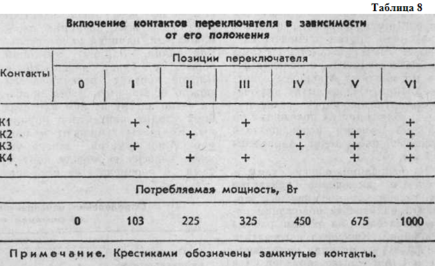
The circuit of the inclusion of the helices of the TET is shown in Fig. 25. Switching of the switch contacts and the power consumed by the burner type EC4-145-1.0 with a power of 1 kW are shown in Table. 8.
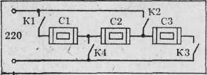
Fig. 25. Scheme of switching the spiral TEN by a seven-position switch to a three-helical burner type EC4-145-1,0: К1 - К4 - switch contacts; С1 - СЗ - spirals ТЭНа.
The possible malfunctions of the burners and their mode switches are analogous to the faults in the hotplates. To replace or repair the design of the Electra-1001 plate provides easy access to any element of the electrical circuit.
Before opening the plate, it is necessary to disconnect the power cable from the mains.
The worktable of the electric stove rests on the frame and is attached to it at four points in the corners. In the left and right front corners, the table is fixed with self-tapping screws, and at the rear wall of the frame it has hinges. Having turned out self-tapping screws, the desktop can be lifted up like a piano lid and propped up with a special steel rod, the lower end of which is hingedly fixed inside the board body at the right wall.
Before removing the burner, it is necessary to detach the wires with spring-loaded tips from it and remember the order of their location on the burner terminals. For this purpose, the ends of the wires have colored marks that are uniform for all the burners. Elements for attaching the burner are shown in Fig. 26. To release the burner, you must unscrew the nut of the grounding wire and the nut holding the clamp. We will take into account that a rusty nut is easier to turn off if a drop of engine oil or kerosene is introduced into its thread.
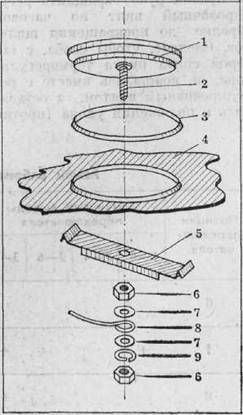
Fig. 26. Elements of fastening of a cast-iron ring on a working table of an electric cooker: 1 - a ring: 2 - a hairpin М6х40; 3 - ring of the cuff; 4 - working table, 5 staples; 6 - a nut; 7 - a washer; 8 - grounding wire; 9 - spring washer
The installation of the new cooking zone is carried out in the reverse order.
To remove the mode switch, you need to disconnect the wires and wires leading to it and go to the outlet and the switch, then remove the six self-tapping screws securing the control panel and remove it.
Under the control panel is the second panel on which all the switches are fixed. Turning out two screws from the front of this false panel, you can remove the switch.
After repair or replacement of the switch, remove the removed parts in the reverse order.
Heating elements, heating the oven, are fixed under its arch and under the bottom. The cabinet with TENamp is insulated with glass wool or mineral wool, which should not be taken with bare hands: fragments of its fibers easily dig into the skin and cause itching. The top heater of the frying cupboard is fixed with a special bracket under the cover on the back wall of the electric stove. To access the heater it is necessary to unscrew the two self-tapping screw at the top of this cover, to raise its top for the outlet of its lower edge from the grooves in the back wall of the electric stove. Disconnect the wires from the heaters, bend the pliers with the tie rods and remove the TEN together with the bracket from the frying cupboard.
The lower heater is located under the steel bottom of the frying cupboard. To access the heater, you need to unscrew the two self-tapping screws that secure this bottom from the side of the oven door, raise the bottom and pull it outward. The attachment point and the terminals of the lower heater are similar to the upper one and are also located under the back cover of the plate.
Electric irons. When obtaining an iron, it is useful to know its characteristics, which are encoded in the letter designation: UT - iron with thermoregulator; UTP - with thermostat, steam humidifier; UTPR - with thermostat, steam humidifier and sprinkler; UTU - weighted with a thermoregulator.
The digits following the letters correspond to the power (400 or 1000 W), followed by the designation of the mass (0.8 to 2.5 kg). For example, УТП1000-1,8: an iron with a thermoregulator and a steam humidifier with a power of 1 kW, weighing 1.8 kg.
The maximal warming-up time of the soleplate of the iron to the set temperature is from 2.5 minutes (for an iron of UT 1000-1.2) to 7.5 minutes (for UTU1000-2.5).
The main elements of the iron - aluminum or cast-iron sole with pressed tubular electric heater (TEN), housing and automatic temperature controller.
The axis of the thermostat control knob is removed from the iron housing, the control knob is provided with a mode dial.
To control the state of the heater, an alarm lamp is mounted in the iron handle. When the iron is heated to the set temperature, the heater switches off automatically and the warning light goes out.
The signal lamp with a voltage of 3.5 V (current 0.26 A) is powered by a voltage drop across a segment of a nichrome spiral connected in series with the TEN. This spiral is isolated by porcelain bead tubes.
The terminals of the heating element, the spiral, the cartridge of the warning light and the power cord are connected to a three-contact pad inside the rear part of the iron handle. The socket is closed with a plastic cover.
The iron thermostat operates on the principle of a high-speed switch controlled by a bimetallic plate (Fig. 27). Bimetallic plate 1, heated from the soleplate of the iron, bends and slowly squeezes the left-over end of the contact plate 2. Once the plane of the plate 2 Moves above the left point of the flat spring stop 3, the latter will instantly press the plate 2 up and the thermoregulator contacts will rupture. Cooling down, the bimetallic plate will slowly bend downward, and all the elements of the thermostat will come to their original position. In this case, the inclusion process will also be instantaneous.
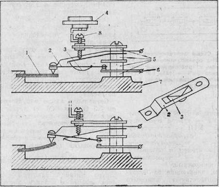
Fig. 27 Thermoregulator iron: 1 - bimetallic plate; 2 - movable contact plate; 3 - spring of a movable contact; 4 - thermostat knob; 5 - insulating washers; 6 - fixed contact plate; 7 - sole of iron; 8 - adjusting screw
Thermostat knob, moving the left point of the spring stop 3 relative to the plate plane 2, regulates the temperature of the entire mechanism.
In irons with a steam humidifier, a flat water tank with a drop-forming valve is mounted, and in the sole there is a steam generating compartment or labyrinth channels.
To reduce the temperature of the iron housing in its design, it is possible to touch the body with the sole not around the entire perimeter, but only at several points. Through the cracks in the body fabric fibers fall into the litter of the thermoregulator contacts and create the smell of burning. Therefore, it is recommended to clean the iron once every 1-2 years.
To disassemble the iron, release the terminal block from the wires connected to it and unscrew the two screws securing the sole to the iron casing. These screws are located under the handle of the thermostat. The handle of the thermostat is pressed against the body of the iron by two snap-fit springs. To remove the handle, simply pull it away from the body.
In UT-type irons, the body to the sole is fixed not with screws, but with two nuts with M4 thread screwed onto the studs. The nuts are recessed in the casing, and they can be turned off only with a socket wrench.
At any dismantling of the iron, it is necessary to check and tighten all the screws inside the case, to clean the contacts of the thermoregulator by pulling between them a narrow strip of fine-grained sandpaper.
The power cord, as a result of constant bends, often breaks down at the point of insertion into the handle of the iron. Such a cord does not need to be replaced, it should be cut off at the break point and re-sealed in the terminal block.
The cause of insufficient heating or overheating of the soleplate of the iron can be a knocked-down adjustment of the thermostat. The broken adjustment of the thermostat in an UT type iron can be restored by the following method. Pre-turn the knob of the thermostat counter-clockwise until it stops, setting it to minimum temperature. Disassemble the iron by separating the sole with the thermostat from the iron housing. With the index finger of the left hand, lift and lower the end of the movable contact plate to the point of contact with the bimetallic plate. In this case, you can hear and even feel the finger of the switching on and off contacts. Continuing to click the contacts, the screwdriver (in the right hand) rotate the adjusting screw clockwise until the clicks stop. Make sure that the bracket with which the handle of the thermostat is removed does not rotate with the adjusting screw, but remains in the stop position (counter-clockwise). Then turn the adjusting screw half a turn back (counter-clockwise). Clicking should reappear. This position will correspond to the correct setting for the minimum temperature of the thermostat.
The same method of adjustment is applicable to other types of irons. The difference is only in the design of the mechanism for transferring rotation from the handle of the thermostat to its contact plates.
The iron with the burnt TEN repair is not amenable, since the TEN is pressed into the soleplate of the iron. From such an iron is useful to remove the spare parts for the cord, thermostat and light bulb.
Rosters.Such devices of infrared radiation are widely used for the preparation of sandwiches, toast, small portions of shish kebabs and other dishes. In the case of the device, heating elements (open spirals or heating elements), a mode switch, a time delay device and a grid for placing the processed products are mounted.
The location of the heaters in the most widespread P-2 roster and its electrical circuit are shown in Fig. 28. Mode of operation of the roaster is considered in Table. 9.
The most unpleasant malfunction in the roster could be the burn-out of the TEN, the replacement of which can only be found in a specialized workshop, and then, if lucky.
In this situation, it is necessary to redistribute the heat load between serviceable heaters, keeping the roster working at all positions of the switch, or at least to sacrifice one of the regimes that have the least utility. Having solved the issue with the choice of modes, it is necessary to think over the necessary changes in the scheme for switching the heaters. For example, it is decided to do without a regime of long-term heat preservation (switch position III). We dismantle TES C5 (lower row) and put it in place of the burnt TEN. The points A and B are connected by a bridge. This change will save the work of the roster at all positions except the third one. At the IV position, the role of the absent TEN C5 will be played by the TEN C2.
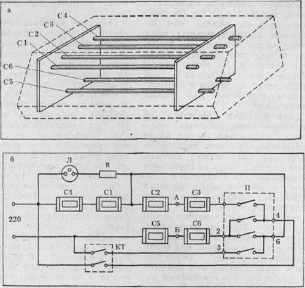
Fig. 28. Location of heaters in the P-2 roster (a) and its electrical circuit (6): С1 - С6 - spiral TEN;
P - mode switch; P - limiting resistor; CT - timer contacts
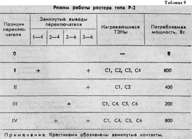
You can also dismantle the TEN C2 and put it in place of the burned out one. The points A and B are connected by a bridge. Roster will keep the work on all modes with the only difference that in position 1 instead of the withdrawn TEN C2 will operate TEN C5.
There are other options for changes in the scheme, which you can think through yourself.
TEN terminals are connected to spot welding wires. When permitting the TEN, the wires should be bitten not at the very terminals, but at a distance of 40-50 mm from them, so that the conductors are soldered at a distance from the ends of the heaters and does not melt from heating them.
Connections of heating elements on the opposite side of the switch are made with a band-shaped shank. It should be cut at a distance of 15-20 mm from the TEN outlet. In the boring hole drill a hole under the screw MZ, with which you can reliably connect the shredder with the wire.
Electric coffee grinders. The electric coffee grinder of shock action (models IP-30, Mikma, Zarya, etc.) breaks coffee beans with a double-bladed knife rotated at high speed. In the grinder body there is an electric motor with an interference suppression device and a blocking device disconnecting the motor at open the lid. To reduce noise, the engine is fixed in rubber shock absorbers. The required speed is achieved by the mode of short-term motor overload (30-50 s). The power consumed by the engine is 125-150 W. Compare: the power of the desktop fan is 22-45 W. Increasing the grinding time or several successive grinds with this overload results in the combustion of the insulation of the motor winding. It is not uncommon for the engine to shut down due to loosening of the contacts in the locking device or the power button.
To disassemble the grinder (for the example of the above models), it is necessary to unscrew the two-blade knife from the armature axis of the engine, which can be done by holding the anchor from free rotation. For this purpose, at the bottom end of the armature axis, the slot for the screwdriver is cut, and in the center of the bottom of the grinder body there is an opening for accessing the screwdriver to this slot. Rotate the two-bladed knife in the direction in which it rotates when the state is on! Beware of tearing the slot for a screwdriver in the armature axis: without its help, the coffee grinder can not be disassembled. Under the removed knife in the center of the cup for grains will open the hexagonal plastic gland head, preventing the ingress of ground coffee inside the grinder. Turn this head counterclockwise to / 4 Turnover with a socket wrench (or carefully, so as not to crush the head, - pliers) will release the cup. Under the cup, press the shim spacer. By removing it, we get access to the engine mount. Pressing the clamp, pressing the engine through the rubber shock absorbers to the bottom of the grinder body, slightly turning this bracket in either direction (counterclockwise or clockwise), release the engine and remove it from the grinder body together with the blocking device.
The burnt stator winding of the engine, executed on the frame, can be rewound. The malfunction of the locking device and the associated power button is usually eliminated by simple bending of the contact plates.
Vacuum cleaners. Depending on the purpose of the vacuum cleaners are made of two types: NP - floor and PR - manual (rod, car and vacuum cleaners-brushes).
The main parameters of vacuum cleaners are given in Table. 10.
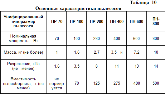
Note. The capacity of the dust container is determined by the amount of dust at which the air flow will decrease by 60% of the original value.
All models of vacuum cleaners have a repairable design, convenient access to the places of maintenance and repair.
In the case of the vacuum cleaner the air-sucking unit is fixed - a high-speed electric motor with a centrifugal fan.
Typical malfunctions of the vacuum cleaner are a break in the cord, a disruption of the reliable contact of the brushes with the collector of the electric motor, a malfunction of the switch, jamming of the discs of the centrifugal fan.
In order for the vacuum cleaner to work long and reliably, it is necessary to clean the dust bag and filters in a timely manner. When the dust container is full, the vacuum decreases sharply, which leads to an unproductive increase in the cleaning time, energy consumption and accelerated wear of the vacuum cleaner.
The vacuum cleaner requires constant attention. It is necessary at least every two years to change the lubrication of the bearings of the motor of the vacuum cleaner, to annually check the condition of the graphite brushes.
In order to change the lubricant, the air intake unit must be removed from the vacuum cleaner housing, the fan housing must be removed, the nut on the motor axis can be loosened (the nut may have a left thread), remove a set of alternating aluminum fan disks (with blades and without blades) from the axis, disks one from another. It is necessary to remember the order of the disks and bushings location in order to install them strictly in the same order during assembly.
Then, remove the screws securing the motor bearings, remove the covers. Remove old grease and rinse bearings with gasoline, making sure that gasoline does not get on the winding. Fill bearings with lubricant TsIATIM-202 (available in auto parts stores). In extreme cases, you can refresh the lubricant without rinsing. To do this, after filling the bearings with a new lubricant for a few minutes, rotate the motor armature by hand so that the remnants of the old grease in the bearings mix with the new, then remove this lubricant and refill with a new lubricant. Assemble the air inlet unit in the reverse order. Rotate the armature by hand to make sure that the fan rotates freely.
When the wear of the graphite brushes and the decrease in the force of the springs pressing them against the collector, the brush arcing, wear and overheating of the collector increase. It is allowed to sparkle at the edge of the brush no more than a filamentary weakly luminous line.
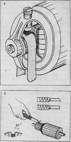
Fig. 29. Lapping the brushes of the electric motor (a); winding reservoir (b)
Worn brushes must be replaced. A new brush should be rubbed to the collector so carefully that the collector touches the entire end face of the brush. This is done by pulling a fine-grained skin between the brush and the collector abrasive side of the skin to the brush. In order not to wear off the edge, the skin should cover the collector along half its circumference (Figure 29, a).
The gaps between the lamellas (plates) of the collector must be cleaned of graphite and copper dust with sharp-pointed match, and the collector wiped with cotton wool soaked in gasoline. If the collector, as a result of many years of work, is worn out so that the insulation between the lamellas begins to protrude above the contact surface of these lamellas, the collector should be increased, that is, cut the protruding interlamel insulation to a depth of 0.5-1 mm (Figure 29, b).
Cutter for road construction can be made from old hacksaw blade, sharpening its end at an angle of 30-40 °. After the roadworthiness, the collector must be cleaned from the burrs with the smallest peeled oil with the rotating electric motor at low speed (with reduced supply voltage).
About repair washing machines, refrigerators and other household electric appliances will be told in the subsequent releases of DIY.
Electric stoves are increasingly included in the everyday life of urban residents. This is due to the expanded capabilities of such equipment and the ban on the supply and installation of a gas system in multi-storey buildings. Let's consider how to properly connect the electric cooker.
Types of electric stoves
There are several classifications.
According to the material of execution:
- Enameled. in such models there are two types: pancake (cast iron), spiral. There are combined options with connection to gas and electricity.
- Glass-ceramic. The heating element in such plates is a spiral, corrugated tape, halogen lamps.
- Induction. They can be attributed to a subspecies of glass-ceramic plates, but instead of a heating element, an electromagnetic coil is built in.
By design:
- Stand alone. This technique can be equipped with an oven.
- Desktop. Popularity is due to the compactness, mobility. Often the connection of an electric cooker of this kind is used in the country. There are models with built-in oven.
- Built-in. This technique has gained immense popularity due to its ergonomics. The existing range allows you to fit such equipment into any interior. Typically, this technique is divided into a cooking surface and an oven.
By the number of contacts: from one to six.
By intensity of use:
- household;
- professional.
By power consumption:
- low-power (with the ability to connect to a 220 V network);
- powerful (connection of an electric plate with own hands to 380 V).
By type of management:
- mechanical;
- sensory.
As you can see, along with the classic models in our time you can buy and "smart" equipment.
Consider how each type of household equipment of such a plan works.
Design features. Principle of operation
Each electric stove has its own design features.
Enameled
The heating element is a spiral made of metal with a high specific resistance. The principle of operation is based on the release of thermal energy as the current passes through the resistive heating element. This is typical for solid (cast-iron) models, and for spiral ones. There is only one difference: in the first variant, the heating element is inside the burner.
Glass-ceramic
The principle of operation is the same as in enamel plates, with the only difference that the heating element can be not only a classical spiral, but also a corrugated ribbon, halogen lamps.
Induction
But this technique is different in principle. The heating element is an electromagnetic coil, which, passing a current through itself, creates a field. It, in turn, forms induced high-frequency currents in the dishes. Guidance occurs due to lines of force through the bottom of the dishes. Therefore, for such plates you need specialized kitchen utensils.
Apparently, the principle of operation of induction models differs significantly from other options. Which technique is better?
Advantages and disadvantages
The connection of the electric plate to the network is inevitable regardless of the type. Let's consider each variant from the point of view of merits and lacks at operation.
Enameled
They differ in simplicity of construction, moderate cost and easy repair at a low price. For washing, ordinary, affordable cleaning agents are used. As for the shortcomings, an open spiral - the danger of getting an electric shock at the time of operation, often requires the replacement of a spiral. For cast iron minus - a long time of heating and cooling, respectively, increased electricity costs.
Glass-ceramic
The cooking surface has a high thermal conductivity, which makes it possible to heat dishes and food much faster than the classical version does, and this significantly reduces the cost of electricity. The possibility of setting the exact heating. The heating element is protected by a glass-ceramic coating, which significantly extends its life. Care of the surface is much easier, it has a perfectly flat plane. The price of such a plan is much higher, more expensive and more difficult to repair, abrasives and cleaning powders are contra-indicated for washing, special dishes with a flat, smooth bottom are required for cooking. If the model has low sides, then when it spills food, it can leak to the floor.
Induction models
In terms of energy savings, the most advantageous option. The burners start to heat up only when there is a pan on the stove, if it is removed, an automatic shutdown occurs. Otherwise, this type of technology has the advantages of glass ceramic models, but the price for repairs and the equipment itself is much higher. Moreover, to the dishes one more requirement is required - magnetic properties.
When choosing a particular model, you should pay attention to the technical data, to find out whether it is possible to connect the electric plate to the existing wiring (outlet).
Important characteristics when choosing
Acquiring new equipment, should rely on a number of technical data:
- Dimensions. It is necessary to measure 3 parameters: width, depth, height.
- Power consumption. Depending on the manufacturer, model, availability of the oven, it can range from 1.5 kW to 8 kW. It is better to take a class no lower than "A". Such equipment will save on power consumption. These data are indicated in the passport for the equipment.
- Equipment. The presence of a cable and a plug from the factory. Most often they are absent.
All other parameters are selected based on personal preferences.
 Having identified with the model, perform an audit of the existing electrical wiring. If the power of the equipment does not coincide with the section of the cable, it will be necessary to replace it.
Terms of connection
Modern plates have a lot of power, so before you buy the chosen model, you need to evaluate the existing wiring system. Most often this technique is sold without a plug and wire, because the connection of the plate electric plants are provided in three ways. The required one is selected at the installation site, to which a number of requirements are made.
It is necessary to have a free end of the wire in place of up to 2 meters. This will allow you to move the repair work or for washing the floor under it.
Must comply with the declared power consumption. Even better, if there is a reserve. This is especially true for intensive use of cookers and ovens.
The cable must be integral, free of adhesions and joints.
The wiring for the plate is supplied separately, and a separate automaton must be provided in the shield.
Regardless of the model, household appliances are often connected through a power outlet. But first, let's see what cable is needed to connect the electric cooker.
Wire selection
In multi-apartment buildings, single-phase connection of slabs is most often envisaged, so builders leave a free end of the wire with a cross-section of 4 mm 2. Such parameters are suitable for plates with a power not exceeding 13 kW. 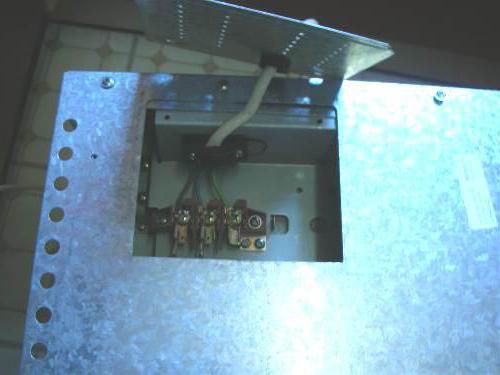
If the wiring is not provided, it is obsolete, then it is necessary to select the correct wire for connecting the electric cooker, which must meet the following parameters.
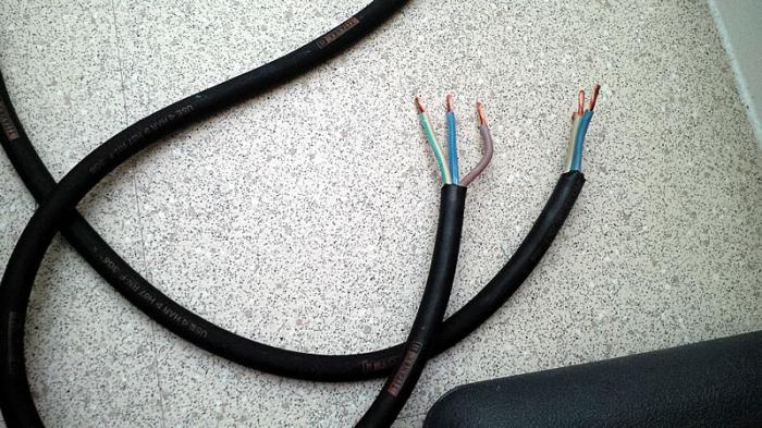
The veins should only be copper (established by the regulatory document of the PUE 7.1.34).
The number of cores is important. For apartments most often there is a single-phase connection, the cable for it is taken three-core (phase L, zero N, PE ground). In private houses, a three-phase, five-core cable (three phases L1 L2 L3, zero N, PE ground) can be provided.
For a 220 V network, there must be at least 6 square meters. mm, according to SP 31-110-2003 (item 9.2). This is an average value, the value can vary in both directions, depending on the technical data of the plate itself. For three-phase installation, the cable must be a five-core section of at least 2.5 square meters. mm. Determine the cross-section of the cable by using special calculators or tables.
Cable brand is required VVG; VVG-ng; PVA; ShVV. To connect the plate to the network, you can use PVA or KG.
Wire laying must be carried out separately.
It is necessary to have a separate machine in the shield. RCDs for normative documents you can not put it for home appliances. But considering that the electric stove is an increased source of danger, it is better to provide. The automatic machine for a single-phase installation is selected with a rated current of 32 A (RCD at 40 A), for three-phase - a three-pole automatic machine at 16 A, a RCD of 25 A.
The cable for connecting the electric cooker must be laid in a separate line, it can not be hung with other points (sockets, lighting). Most often, hidden wire is used.
Selection and installation of power outlet
Determining which cable is needed to connect the electric stove, choose a power outlet. 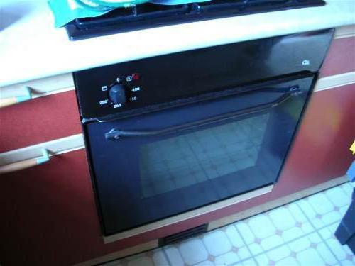
It must meet the following requirements:
- the rated current of the socket and plug must correspond to the parameters of the machine and the number of wires of the wire;
- the form of the power outlet depends on the method of laying the cable (hidden or open);
- should buy a product made of high-quality non-combustible materials.
Consider a number of points for installing the outlet:
- installation is carried out on a flat, non-flammable surface;
- do not install near hot surfaces, heating system, water supply;
- the connection of the conductors must be done according to the scheme, without confusing the colors;
- screw terminals must firmly fix the contacts;
- after installation, check for a short circuit.
After installation, the sockets begin to install the equipment itself.
Installation and connection of the electric cooker
After delivery of the equipment, it should be unpacked and checked for completeness, no visible discard. Before you start, it is worthwhile to carefully study the instructions and the wiring diagram. Remove unnecessary components, set by level.
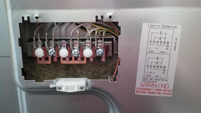
Unscrew the panel covering the terminals on the back of the equipment. There are also duplicated three connection schemes.
As already mentioned earlier, rarely do manufacturers supply household models with a wire and power plug. Therefore, the purchase of a cable and a power outlet with a plug is carried out independently. Let's consider three ways how to make connection of an electric gas cooker with your own hands.
Single-phase
With this installation, the phase (red) is connected to terminals L1, L2, L3. Since the wire is three-core, copper pins are installed on the pins (they come complete with equipment). On N1, N2 set a zero (blue) and a copper jumper. PE - earth (green). All the contacts are tightened, the cable is fixed with a special clamp. The lid is installed back. There are 3 contacts in the socket: upper - ground, two lower - phase and zero.
Three-phase
It differs from the previous phase connection. There is a wire for each terminal. Observe the color according to the scheme. All the rest is made analogous to single-phase.
Two-phase
At phase L1, L2 we put a jumper and connect one of the ends of the phase, on L3 - the second. The rest of the installation is similar to the previous two.
After installation, it is necessary to perform a test run according to the instructions on the equipment.
 Connecting the electric cooker independently will not cause difficulties, if you follow the instructions and safety during installation. All work must be carried out with a de-energized system.
Features of mounting of some brands
Connection can be made both on a single-phase circuit, and on three-phase. It all depends on the power supply. All the steps are described above. The connection also does not have any features and is implemented according to the general scheme.
It is worth drawing special attention for warranty obligations. Incorrect installation can lead to equipment failure, and this will be the reason for the refusal of the service center to carry out a free repair. Therefore, if you are not sure of your abilities, it is better to carry out installation by a specialist, who has a special license for such work. In the passport a mark is placed on the connection in case of misunderstanding.
Connecting the gas cooker
The design of this technique makes it possible to use both the electrical network and the gas. There are two versions: with mounting to the gas distribution network and gas bottle. It should be noted that for the use of gas equipment in apartment house, in which such a system is not provided, a special permit will be required. 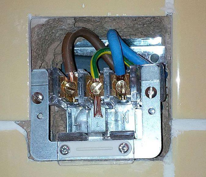
The rest can be noted two important points: connection to the gas distribution network must be performed by a specialist gas supplier company, which places an appropriate mark in the passport. In the future this organization conducts maintenance equipment. Installation to the network does not impose special requirements. For a sufficient outlet with 16A grounding.
Conclusion
As you can see, you can independently connect the household electric cooker yourself.
But if you are not confident in your abilities, it is better to turn to a specialist. In the future, this will reduce the cost of paid repair of equipment due to improper installation.
So, we found out how to connect the electric (gas) plate with your own hands.
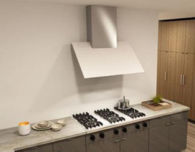
Today, hardly anyone will dispute the dignity of electric cookers, which in many kitchens replaced traditional gas stoves. The choice of a product of one type or another depends primarily on the supply of natural gas and the presence in the dwelling of a developed gas main.
Owners of gasified houses will certainly prefer a gas appliance, and an electric stove can be used as an alternative. If there is no possibility to let in a residential individual house natural gas, then any homeowner will use an electric stove instead of using a device operating on a balloon (propane-butane), liquefied gas.
In addition, there are undoubted advantages and disadvantages of electric stoves, which are associated with both design, aesthetics and ergonomics, and with the functionality of both products.
The main advantages of electric cookers are:
- greater energy efficiency and the lack of radiation of excess heat energy, for neutralization of which many owners install a window, single-block air-conditioner in the kitchen;
- when operating an electric stove, it is not necessary to carry out a periodic inspection of the technical condition, which according to the existing rules can only be carried out by specialists of gas firms;
- greater operational safety of electrical household appliances in comparison with gas appliances;
- the possibility of self-connection of an electrical appliance, which is much easier to perform than a gas appliance and unnecessary calling a specialist to verify the correct connection.
Some critics consider the lack of electric stoves their high cost in comparison with gas. However, this issue is rather controversial - today in the market of consumer devices you can find budget options, the price of which is at the level of gas appliances. At the same time in the "premium" class you can find gas equipment, which at its price far exceeds the most widespread electric models.
Types of electric cookers
Modern household electric stoves are divided into two categories, each of which is characterized by the type of cooking surface:
- products with enamel top and cast iron burners;
- models with glass ceramic hob.
To the disadvantages of any models, outside their category, one should include some thermal inertia - their cooking surfaces slowly reach the working temperature and also cool slowly. Therefore, set the required temperature regime can be quite difficult. Because of this, the budgetary options provide for a fixed adjustment of the thermal capacity - for three ... 6 positions.
The undoubted advantage of products with cast-iron burners is their more democratic price. Models with a glass ceramic surface have an even cooking surface. As heating elements These products can use tape, halogen or induction devices, which are much easier to perform power adjustment.
Therefore, cheap glass-ceramic cookers have a simple rotary regulator, and expensive models can be equipped with electronic or touch controls. In addition, the design of the hob has evolved decades ago and is now determined by the type and size of the heating elements. The appearance of the plates with the ceramic glass ceramic panel is constantly improved, they have a more stylish look and greater ergonomics.
The drawbacks of glass-ceramic models include the inconsistency of the size of the hob to the bottom of the cookware. However, this disadvantage is compensated by the use of several individual heating elements.
Today the most popular brands of household kitchen electric cookers are Beko and Vestel (Turkey), DeLuxe (Russia), Gefest - Gefest and Atlant (Belarus), Ardo, Candy, Indesit and Zanussi (Italy), Blomberg, AEG and Bosch (Germany), Electrolux (Sweden).
Of course, the quality of any product, regardless of the brand, is curled from compliance with the rules of operation. At the same time, the correct connection affects not only the performance characteristics, but also the safety of use.
It should be noted that electric stoves are produced with a voltage supply of both 220.0 volts and 380.0 volts. For the city apartment should choose products of the first category. If a person lives in a private house and has a three-phase supply, then preference should be given to electric stoves designed for 380.0 volts.
Rules for the installation of electric stoves
To connect a plate follows the person who has the minimum electrotechnical skills and has the general representation about rules of operation of electroinstallations and the safety precautions at work with electrodevices.
After this, you should carefully read the instruction manual for the specific model, which should be completed with any new electric stove. It should be borne in mind that it is wrong. Performing the work can lead to de-energization of the entire entrance, burnout of wiring and damage to the product.
In addition, most companies - dealers and service centers may refuse warranty repairs, if the installation was made not by the specialists of the company through which the product was purchased.
The tool will require:
- pliers with insulated handles;
- side cutters (cutters) with insulated handles;
- screwdriver Set;
- indicator screwdriver;
- with a maximum measuring range alternating current 500.0 ... 1000.0 volts.
After this, it is necessary to conduct a separate electric line, through which only the electric stove will be powered. The type of the power line depends on the way the power is supplied to the electric stove. Plates designed for 220.0 volts are connected using a single-phase circuit; models designed for 380.0 volts can be connected via a three-phase or rather rare, two-phase connection schemes.
In addition, when connecting an electric cooker the following requirements must be met:
- power supply is provided by a copper cable, the number of cores of which depends on the connection scheme;
- in the circuit it is necessary to provide for the installation of a separate circuit breaker and a protective shutdown device;
- plate body must be ground through water pipes not allowed.
Connecting the electric cooker according to different schemes
Most modern manufacturers of electric stoves supply their products to the sales network without bundling the power cord. This is due to modern electrical safety requirements, which involve the connection of high-power devices without a grid method - using special terminal blocks.
This method has two main advantages:
- the supply cord can be selected of an arbitrary length;
- it is possible to replace the individual machine with fuse (insert).
If the length of the cord does not exceed 6.0 meters, then the electrical cross-section of each core can be taken equal to 4.0 square millimeters. For longer lengths, the minimum cross-sectional area increases to 6.0 square millimeters and the installation of the fuse-link is prohibited, and power is only supplied through.
In principle, an electrical appliance can be connected and using a special pair of "plug-socket". However, this electric fittings must be designed for a current of at least 32.0 amperes, and the use of conventional household plugs is prohibited.
Single-phase connection
Single-phase connection (Figure 1) is most common in urban apartments of multi-storey buildings. For its implementation, it is necessary to install the jumpers in the terminal box (located on the rear panel) of the electric cooker in an appropriate way. All modern models are equipped with jumpers of the required cross-section. If there are no jumpers, then they must be purchased at the electrical shop or cut out of the copper core themselves. The minimum electrical cross-section of the bridge is 6.0 square millimeters.
According to the scheme, for single-phase connection it is necessary:
- terminals 1-2-3 to be connected by jumpers and connected to the phase conductor (brown, gray or black) of the supply cable;
- connect terminals 4-5 to each other and connect to the neutral conductor (usually painted in blue);
- terminal 6 is connected to a grounding cable - for a single-phase network with a voltage of 220.0 volts, this wire usually has a smaller section and is colored yellow or green.
When making all connections (wires to terminals and jumpers between terminals), a reliable electrical contact must be provided, for which the nuts in the terminal box must be tightened well. If the contact is defective, the connection will warm up, sparking, which will lead to a minimum of insulation burning in the terminal box, and a maximum - to a fire.
Connect the power cable to the plug as follows:
- the phase wire is connected to the plug (terminal) "L";
- zero - to the plug "N";
- grounding - to the plug indicated by the conditional ground symbol (in some products the grounding contact is marked "earth" or "PE").
Two-phase connection
The two-phase connection (Fig. 2) is used quite seldom and can be performed only in residential premises if there is a three-phase network in them. At the same time, the electric burners will be connected to two phase conductors, and one phase will remain unloaded.
The order of installation of jumpers, connection to a plate of a cable and its connection with a plug the following:
- terminals 1-2 or 2-3 are connected by a jumper and connected to the first phase conductor;
- the free phase terminal (3 or 2 depends on how the jumper is installed) is connected to the second phase conductor);
For plug-in connection of the electric stove on a two-phase circuit, it is necessary to purchase a "plug-socket" kit for supplying three-phase equipment, with one plug of the plug being unused.
Three-phase connection
Three-phase connection (Figure 3) requires a three-phase network and is mainly used in individual houses. As is known for their course of general electrical engineering, the voltage between phases will be equal to 380.0 volts, and between any phase and zero is 220.0 volts. It requires four or five core cables.
The connected cables to the terminal box are as follows:
- between the phase terminals (1-2-32) the jumpers are not installed, and each terminal is connected to the phase conductor;
- the installation of jumpers (4-5) and the connection of the zero and ground wires is similar to the one-phase circuit.
When doing electrical work yourself, you should know that some models terminal box The connection is made to the contacts located on the back panel panel.
Cost of connection of electric stove
Before you do it yourself, you should call the service center and ask how much these works performed by the specialist will cost. At the same time, the owner of household appliances gets rid of a lot of problems, related both to the costs of time, and to the sometimes poorly executed work.
Usually a repair shop that conducts electric installation work, takes on himself service maintenance and warranty repair of the product.
For example, in Moscow, when carrying out the entire set of works, standard prices are as follows:
- purchase necessary materials and components (excluding their cost) - 350.0 rubles per hour spent time;
- installation and connection of the electrical outlet - 450,0 ... 750,0 rubles per unit (depends on the type of connection);
- installation of wiring with connection to the shield 150,0 ... 350,0 ruble per meter linear;
- installation of an electric stove - 1000,0 rubles.
There are companies that offer to perform the whole complex of works "on a turn-key basis", without the intervention of the owner, for 20.0 ... 50.0 North American dollars. At the same time, a large price refers to equipment with a glass ceramic hob.
In the province, prices are somewhat cheaper. In Krasnoyarsk and Novosibirsk, the cost of wiring and installation starts from 800.0 rubles. In other regional centers, in the Central regions of Russia, many firms offer their services for similar work within 400.0 ... 500.0 rubles.