Remote control of electrical devices. Remotely controlled sockets
Often there is a need for remote control of a remote object, for example, control of heating, alarm a country house etc. Traditional methods of management here will not help. In this case, cellular communication will come to the rescue. But simply taking a cell phone case will not help, a DTMF code decoder is required, which when you press a particular digit on the cellular phone will switch a channel on the decoder. It is this decoder that is presented to your attention.
Basic parameters of the decoder:
- has 10 independent control channels;
- access by password;
- save the state when the power is turned off;
- sound confirmation of events;
- automatic recording of the status of the outputs, if enabled;
- automatic device locking if password access is enabled.
The decoder scheme is quite simple and does not need to be adjusted. All functionality is implemented on the microcontroller PIC16F883.
As a decoder DTMF Signal is a specialized microcircuit of the brand MT8870 . At the output there are buffered cascades on ULN2003 , which allows the relay windings to be connected non-inherently.
I collected the trial version of the device on the breadboard
The scheme provides for the installation of three jumpers, their purpose:
- S1 - Enabling the state of the outputs;
- S2 - Reset the password;
- S3 - Enable password access.
The algorithm of the device is very simple:
We ring the phone and press the buttons on the phone to control the device. If jumper S3 is installed, a password must be entered before switching the status of the outputs (default is 0000). Next, to enable the required channel, press the channel number and the number 1. To turn off, the number of the selected channel and the number 0. For example, turn on and off channel number 5. Press 51, and then 50. If you want to enable all channels at once, press the two asterisks (* *). To turn off all the channels at once - two grids ().
To change the code, we enter this combination: * # * # and followed by four digits of the new code. If you forget the entered code, it can be easily reset to the standard 0000, by setting the jumper S2 for a short time.
As a rule, in country houses There are cases of power outage, as well as short-term disruptions during strong winds. To save the state of the outputs, it is possible to write the status to the non-volatile memory of the microcontroller and restore this state when the power supply is restored. To do this, use the jumper S1.
I want to draw special attention to unscrew the connector for connecting the device to a cellular phone. Different manufacturers differently separate this connector in the phone! If the device does not react, swap the pins, or look for a pin for your phone. The function of an auto-lift is in almost any phone!
A small video review on working with the device
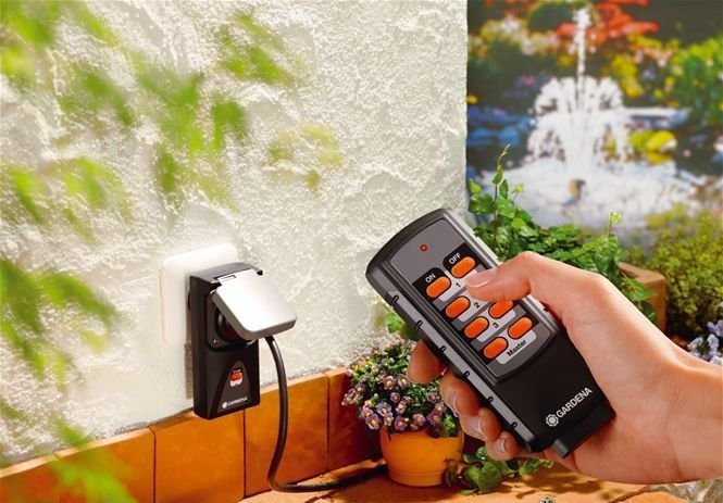
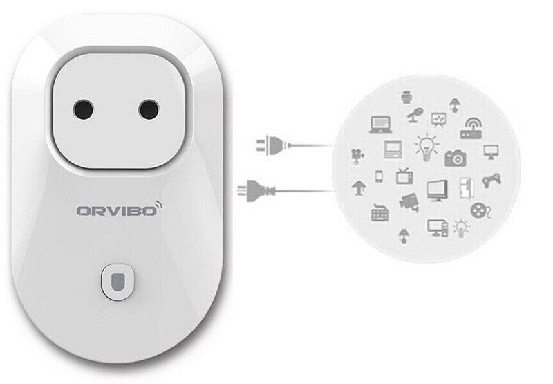
One of the simplest and at the same time effective ways to control the operation of electrical appliances at a distance is to use a device such as a remote control socket (remote control).
Classification
To date, the choice of a remote control socket model should be dictated by the conformity of its technical specifications operating conditions. First of all, we are talking about the power of the device and the maximum range at which its operation can be controlled.
The most popular types of such devices are:
- Wireless socket, controlled by radio. The cheapest and most practical type. To ensure its operation, you need a remote control that allows you to turn on and off individual consumers or their groups from a distance of 30 meters.
- GSM outlet. It is controlled by a mobile phone, so that the distance from which commands can be given to turn it on or off is practically unlimited. This device does not require a special remote, but it can not be used in areas where the mobile signal is weak or muted. In addition, such products today are quite expensive, which is perhaps their main disadvantage.
- WiFi outlet. These devices are controlled via a smartphone or laptop via the Internet. Connecting the outlet to the control device is done using a WiFi router. The shortcomings of these models include a fairly high price with a not too extensive list of additional functions.
Design of remotely controlled devices
It should immediately be stipulated that the devices under consideration can not be fully considered classical power sockets, which are equipped with an additional remote control unit.
Presented on the market remotely controlled models are products that in appearance most resemble an adapter or a socket with a timer. That is, they are equipped with a standard electrical "plug", which is designed to plug the remotely controlled module into an ordinary power outlet.
The main purpose of this device is the opening or closing of the power circuit to which the appliance is connected. This allows you to control the operation of the consumer at a distance, without making any changes to its design or to the supply network device. In fact, the same function is performed by switches with remote control, which are represented on the market quite a large number. The main difference between these devices is that the connection of the outlet is much simpler and does not require intervention in the design of the wiring. This makes it easy to move it from place to place, which is extremely convenient when working with some consumers.
Thus, the remotely controlled socket is inherently a switching device, which upon opening a control panel opens or closes the electrical circuit.
Device controlled by radio channel
The most common version of remotely controlled devices that are part of the domestic electricity network, today is a socket with a remote control.
To ensure reliable transmission of control signals, radio wave transmitters are used in it, which allow the signal to be broadcast at a distance of 30-40 meters and are insensitive to interference. Unlike infrared remote controllers, their radio wave analogs ensure reliable reception of the control signal within the declared range, even if there are concrete walls between the source and the receiver.
To power the remote control, as a rule, 9 or 12 V batteries are used. One such power supply is enough for about a year.
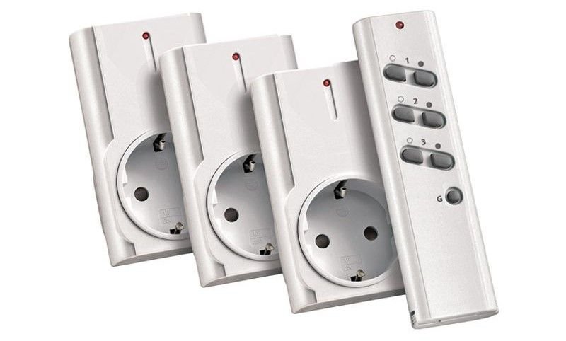
Most models of radio-controlled outlets come bundled, which includes 3 to 5 separate devices controlled from one remote. Accordingly, such a console is equipped with buttons, the number of which depends on the maximum possible number of devices connected to it.
Thus, the radio controlled socket is the cheapest and at the same time quite effective device intended for switching on and off of electric power consumers at a distance.
Connectivity
Before you start, the wireless socket is combined with the remote control, by pressing the corresponding buttons on its case and on the console itself. At this point, both devices are mated to each other via one of the available radio channels, and a light indicator on the socket body signals the successful completion of this process.
It should be noted that the theoretically unlimited number of devices can be controlled on the same radio channel, the only deterrent in this respect is the functionality and convenience of using such a system.
Since the purpose of these devices is to provide remote inclusion and disconnection of any electricity consumers, the scope of such outlets is extremely extensive. An example of their use can be:
- Management of lighting systems of apartments, houses, as well as extensive external territories.
- Switching pumps and fans on and off.
- Management of garage doors and electric locks of entrance doors.
- Opening and closing windows or dampers in ventilation systems.
- Remote control telecommunication systems.
This outlet allows you to command to reboot the equipment in the event of a software failure.
Advantages of using remotely controlled outlets:
- Significantly improve the convenience of managing remote users electric power. Especially this quality is valuable for people with disabilities.
- Easy to connect and operate the device. The ability to move it to any place where a standard electrical outlet is installed.
- No need to make changes in the structure of electrical wiring when installing such a device.
Disadvantages:
- The use of radio waves in some cases can interfere with the operation of devices such as pacemakers or hearing aids. Therefore, before installing the sockets from the remote control, they should be checked for electromagnetic compatibility with the above-mentioned devices.
- Additional elements in the design of any electrical network inevitably reduce its reliability. Connecting such switching devices can cause unintended triggering and unexpected switching on of consumers. It is mandatory to provide for this possibility and take measures to prevent the negative consequences of spontaneous operations.
- It is not recommended to operate the majority of remote control socket models from a distance of less than 1 meter.
- The installation of radio-controlled sockets in the walls, which are covered with sheet metal, significantly reduces the range of these devices.
When selecting outlets with remote control, you should pay attention to their characteristics that determine the permissible operating conditions and the power of the connected load. So, the majority of models of such devices allow connecting electric appliances with power from 1 to 1.5 kW to them, in some cases this is not enough, so it is worth paying attention to more expensive sockets, designed for power up to 5 kW.
As for operating conditions, the sockets with remote control are classified according to IP (degree of protection of the shell) as well as other electrical appliances of this type. For example, the RCS 1044 N socket, which has an IP44 rating, is protected from objects that are larger than 1 mm inside, and spatter falling in any direction. Such characteristics quite allow to use this device in the street.
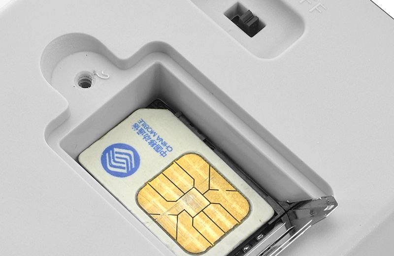
These devices are an extremely convenient variety of remotely controlled outlets. As it follows from their name, you can control the operation of such devices using a mobile phone. For this purpose, a slot for the SIM card is provided in the GSM socket housing.
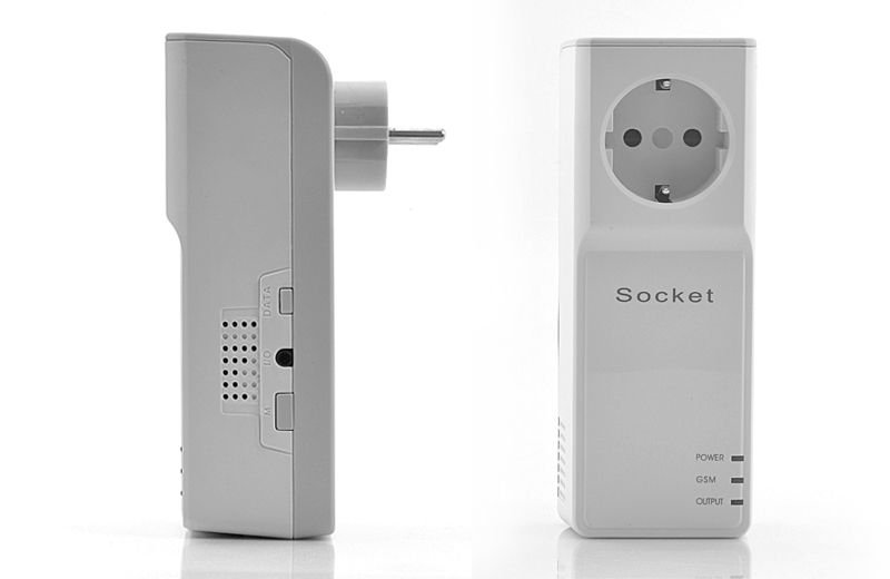
A card provided by any of the mobile operators is suitable. Control can be done by calling or sending a message (empty or with a specific text). It should be noted that the transfer of control commands to such a socket is not possible from any mobile phone, but only from the one whose SIM card number was previously registered in the device's memory. The maximum number of such numbers, as a rule, does not exceed 5 units.
The main advantage that a wireless socket has is the ability to control its operation from any place where there is mobile communication. Another positive thing is that there is no need to use the remote control, which requires power from a separate battery and, in addition, can be simply lost.
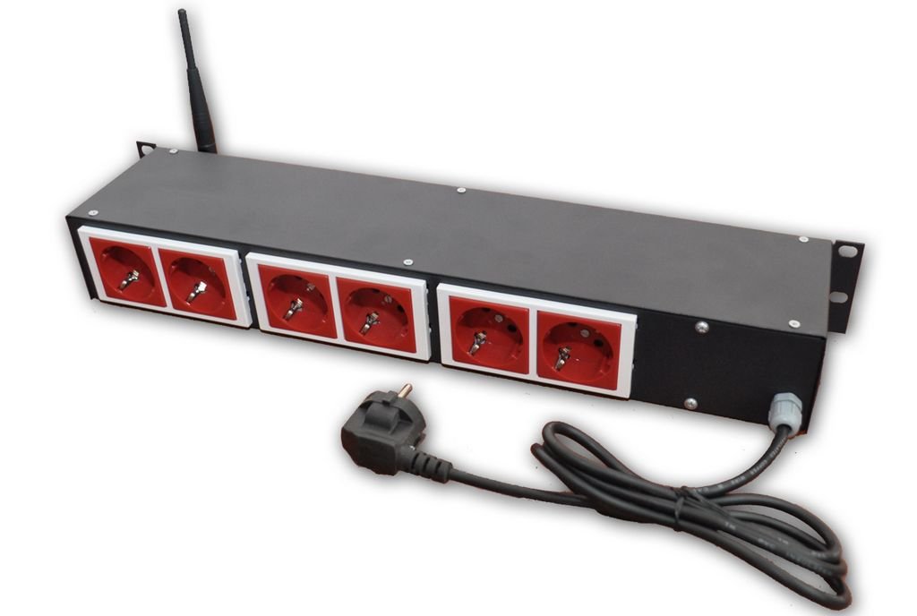
To control the power supply of computers, special modules of GSM sockets are used, which include up to 6 separate connectors. Each of them is assigned a serial number, which allows using the phone to control any device individually or all at the same time.
The drawbacks of GSM outlets include their relatively high price and the need to purchase a sim card. In addition, it is often impossible to determine the current state using the phone, that is, it is unclear whether the device is turned on or off at the moment.
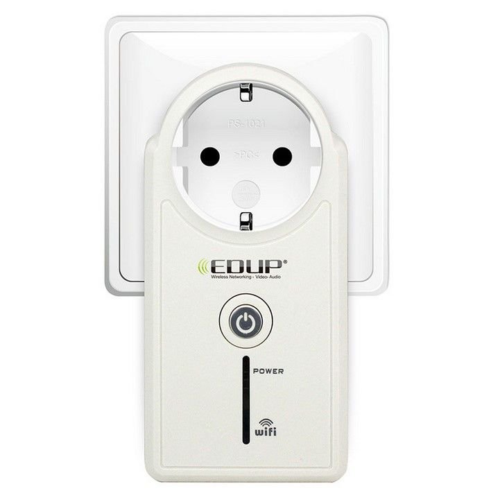
WiFi outlet
The operation of many modern devices can be controlled using wireless WiFi connection. The electric socket is not an exception in this respect.
The main advantage that WiFi sockets have is the ability to control their operation using a computer or tablet via the Internet. In addition, such devices are often equipped with timer functions, which are very convenient to configure in a special mobile application.
To connect and configure this product, you must use a driver package that can be completely downloaded from the Internet or downloaded from the installation disc that comes with the package. After installing the application on a smartphone or tablet and connecting the outlet to your home WiFi network, you need to find the outlet in the smartphone menu. After that, a connection is established between these devices.
The operation of this outlet can be controlled either via the Internet or directly via a WiFi connection. However, for this, the smartphone and the socket must be within the scope of the router.
The main drawback, which significantly limits the popularity of these type of outlets, is their high price with modest functional capabilities.
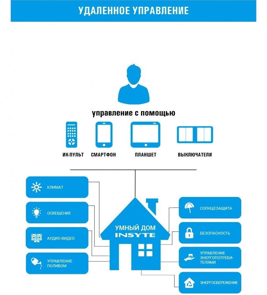
Despite the possibility of connecting to a computer, such a device can not be considered an element of the system " smart House", Because it does not provide full integration into the intellectual management system. In addition, almost all the models of WiFi outlets that are produced today are not able to receive and transmit information about the connected load, current and voltage, as well as the temperature of the environment and other data affecting the operation of the power supply system. Accordingly, the installed program can not make any decisions in case of deviation of these parameters from the norm.
- Control of air temperature in the room. When a certain value is reached, the socket can be turned on or off independently.
- Timer functions.
- Ability to control the outlet from several separate devices (usually at least 5 users).
- The presence of an autonomous power supply, which allows you to save the settings of the device in the event of a power failure in the network.
- Informing the user about the occurrence of emergency situations, such as a sudden increase in temperature or the loss (inclusion) of voltage in the network. In this way, additional duplication of the fire alarm can be implemented.
The remote control system of TVs of type 3-USTST is not compatible with codes with most modern imported and domestic TVs and other equipment. Therefore, the signals sent by old RC-3, RC-4 consoles are not perceived any more modern systems RC-5, RC-6 and higher. Similarly, and the remote control system for older TVs does not respond to signals from modern control panels.
This circumstance is very convenient, since it allows you to use both systems in the same room without causing errors. And based on the codec-set of the KR1506HL1 (SAA1250) and KR1506XL2 (SAA1251) chips, it is possible to make a universal control system household electrical appliances, - lighting, ventilation, etc.
In the literature, DA systems were already offered electric appliances on such an element base, but many of them have specific shortcomings. For example, in L.1 we propose a scheme in which the levels of the binary code for switching programs directly from the output of the microcircuit KR1506XL2 are fed to the switching keys. Of course, this is convenient from the point of view of saving details, but not from the user's point of view. It turns out that there are 16 buttons of the console, each of which corresponds to a certain combination of switched on and off loads. For example, if you want the floor lamp and fan to be switched on, and the chandelier and heater are off, press button 11, and if you need only the chandelier to work and everything else is off, press button 3. It turns out that you need to bind to the console on a string of instructions for use. Well, if you know the binary code, and how its levels correspond to your workloads, then with varying success, you will be able to use such a system. But how to be, for example, your grandmother? But, by definition, such a remote control system should primarily be designed for elderly people who are limited in movement.
It will be much easier if you switch four loads with a five-button remote control, four of which will serve to switch loads, and one to change the status of the load. Such a system can be used not only by a grandmother, but even by a child of preschool age. The decoder circuit is shown in Fig. 1.
The decoder is made in the form of a complete independent module, included in the power grid. To control four loads, electromagnetic relays are used, allowing a current through the contacts up to 5A at a voltage in the circuit up to 250 V.
The switch on the relay, unlike the thyristor, does not distort the shape of the mains voltage and allows controlling almost any equipment. Connector X1 is connected to a standard photodetector for remote control systems of 3-CCTV TVs (Figure 2).
The chip D1 КР1506ХЛ2 is switched on by the simplified standard scheme, in which there are no circuits of adjustments and deenergizing, - only switching circuits of programs are left. Moreover, all four bits are used (conclusions 8, 9, 10, 11). Since the levels on these outputs change according to the binary code law, the unit on pin 8 (at the other outputs of zero) will be on switching on the 2-program, the unit on pin 9 (on others, -down) when switching on 3 programs, the unit on pin 10 (on others, - zeros), - 5 program, and a unit on the output of 11 (on the others, - zeros), - with the inclusion of the 9 program.
The circuit on the chip D1 serves as a source of control signals, and the actuators are executed on the triggers D2 and D3. The triggers are connected by a divider circuit for two, but delays are introduced into the chain of the data input input on the RC circuits C5-R15, C7-R13, C9-R11 and C11-R9. These delays are needed in order to avoid multiple trigger switching in the event of a signal interruption or interference. Thus, each flip-flop, for example D2.1, can be switched to the opposite position only after charging capacitor C5 through the resistor R15 to a logical one.
When any one or four of the above commands are given, a unit appears on the corresponding output of the D1 chip, and when the fifth "status" command is sent, all the outputs of D1 are set to zero. The appearance of a logical unit on one of the outputs D1 leads to the formation of a control pulse using one of the RC-circuits - C3-R2, C6-R3, C8-R4 or C10-R5. This pulse goes to the snowshoe of the corresponding trigger and this trigger changes its position to the opposite.
The fifth command "status" is needed to enable and disable one of the loads independently, without having to turn on or off other loads. Suppose we need to turn the K1 relay off and then off, and yet we do not want to change the state of the other relays. First, we press the S1 button (Figure 3).
The console sends a command and a 1 appears on pin 8 of D1 (Figure 1). The circuit C3-R2 generates a pulse and the trigger D2.1 assumes a zero state. The unit from its inverse output goes to the switch on the transistor VT1 and turns on the relay K1. After this happens, and we release the button S1 of the console, the logical unit remains on pin 8 D1 (Figure 1) and will remain there until we change the state of the outputs by giving another command. If we press S1 again, nothing changes, and turn K1 remains on. In order to turn off this relay we must first set on pin 8 D1 zero. This can be done by submitting another command, or you can reset all outputs of the D1 chip (Figure 1) by pressing the S5 button (Figure 3). At which the code of inclusion of the first TV program is formed, - 0000, and all outputs D1 (Figure 1) are set to the zero state.
Therefore, to turn off K1 we must first press S5, and then release it and press again S1. If you press S5, the unit on the vyv. 8 D1 will be replaced by zero and the capacitor D3 will be discharged through resistors R2 and R18, as well as through the internal diode of the D2.1 chip (the inputs of the K561 chips have back-up diodes limiting the negative voltage emissions).
Then, press S1 and on the pin 8 of D1 a unit will appear again, the C3-R2 circuit will form a pulse that will switch the trigger. To ensure that after a power interruption, for example, caused by a power failure, all relays are set to the off state there are circuits C4-R6 and C1-R1, the first of which forcibly sets all triggers to a single state (zero on the inverse output), and the second, sets all outputs of the D1 chip to zero.
The power supply is unstabilized, its output voltage is about 14V. This voltage is fed by the entire decoder circuit, including the relay and the D1 chip. According to the passport data, the power supply voltage of the KR1506HL2 IC must be 18V, but as practice shows, this chip works well and under reduced voltage.
The control panel layout is shown in Figure 3. This is a simplified typical scheme the inclusion of the chip KR1506HL1, in which only five commands are used.
Microcircuit KR1506HL1 can be replaced by any type of "... 1506HL1" (K1506HL1, KM1506HL1, KS1506HL1, EKR1506HL1) or imported SAA1250. The chip KR1506HL2 can also be replaced by any type "... 1506HL2" or imported SAA1251. Microcircuits K561TM2 can be replaced by analogues of other series, -K1561TM2, KM561TM2, EKP561TM2. And here,
the K176TM2 chip should not be used because its power supply voltage can not be more than 12V. Or, it is necessary to feed it with a lower voltage and do circuit matching levels with D1 on resistive dividers.
The power transformer is a Chinese compact with a voltage on the secondary winding of 12 V. It can be replaced by another similar one. In any case, the voltage at the output of the rectifier (at C13) should not be more than 15.5V (maximum rated power voltage for K561).
Electromagnetic relays can be replaced by others with windings for voltage 12V and pins that allow switching of the network load, for example, relay KUTS-1 from remote control systems of televisions TCTT. Quartz resonator, - from TVs or VCRs. Infrared LED AL 156 can be replaced with any IR LED used in remote control.
The photodetector circuit (Fig. 1) was copied from the scheme of the 3-CCTV system. You can make a photodetector on another element base, for example, on a K1056UP1 chip. The cable connecting the photodetector with the decoder node should be shielded and should not be longer than 1 meter. -Installation of decoder node is performed
partially printed, partially volumetric, on the printed circuit board of the remote control module 3-USTsT. A ready photodetector is also used from the same system. The remote control is assembled in bulk in a small school case. For control, imported instrument buttons are used without fixation (with a nut fastening). You can also use a ready-made RC-3, RC-4 type, changing the keyboard according to the scheme in Figure 3. The extra buttons can be removed or closed by cutting out the rubber contacts.