Calculation of the duct network. Procedure for calculating pressure losses in ducts. Determination of pressure losses at the bends of air ducts
The purpose of the aerodynamic calculation is to determine the pressure loss (resistance) to the movement of air in all elements of the ventilation system - air ducts, their shaped elements, grids, diffusers, air heaters and others. Knowing the total value of these losses, you can choose a fan that can provide the required air flow. Distinguish the direct and inverse problems of aerodynamic calculation. A direct problem is solved in the design of newly created ventilation systems, consists in determining the cross-sectional area of all sections of the system for a given flow through them. The inverse problem is the determination of the air flow for a given cross-sectional area of operated or reconstructed ventilation systems. In such cases, to achieve the required flow rate, it is sufficient to change the fan speed or replace it with another size.
Gases are liquids that do not have a certain volume. The gas has no shape, and it takes the volume of the container in which it is located. They are affected by temperature and pressure. The volume of gas in a closed container is the volume of the container. Two containers of different volume may contain the same mass of gas.
Liquids are liquids that have a certain volume that does not depend on the shape and volume of the container. When the liquid is placed in a container, it takes the form of a container, but the volume and mass remain unchanged at constant temperature and pressure. Liquids can be considered incompressible. The volume will not change significantly under pressure. The volume of the liquid can vary markedly at different temperatures.
Aerodynamic calculation begins after determining the multiplicity of air exchange of premises and decision-making on the route (layout) of air ducts and channels. The air exchange rate is a quantitative characteristic of the operation of the ventilation system, it shows how many times during the first hour the room air volume is completely replaced by a new one. The multiplicity depends on the characteristics of the room, its purpose and can differ by several times. Before the beginning of the aerodynamic calculation, a scheme of the system in the axonometric projection and scale M 1: 100 is created. The main elements of the system are distinguished on the scheme: air ducts, their shaped parts, filters, sound attenuators, valves, air heaters, fans, grilles and others. According to this scheme, the building plans of the rooms are determined by the length of individual branches. The scheme is divided into design sections that have a constant air flow. The boundaries of the calculated areas are shaped elements - bends, tees and others. Determine the flow at each site, apply it, length, plot number to the circuit. Next, choose the trunk - the longest chain of successively located sections, counting from the beginning of the system to the outermost branch. If the system has several highways of the same length, then the main one is chosen with a high flow rate. The cross-sectional shape of the air ducts is accepted - round, rectangular or square. The pressure losses in the sections depend on the air speed and consist of: frictional losses and local resistances. The total pressure losses of the ventilation system are equal to the losses of the main line and consist of the sum of the losses of all its calculated sections. Choose the direction of calculation - from the farthest point to the fan.
Pressure units as the height of a column of water
Pressure is the force per unit area. The pressure exerted by a force or weight of 100 pounds per 10 ft2 is 10 pounds per square foot. Density is the mass per unit volume. Drawing? shows that the measuring scale for pressure can be the height of the liquid column.
Therefore, the pressure can be expressed as the height of the water column. In the case of liquids and pumping systems, it is measured in feet of water. However, the vapor pressure is measured in pounds per square meter. In the case of gases and fan systems, this is measured in inches of water. The term "air" when referred to in a comfortable air-conditioning consists of water vapor and dry air, which consists of the rest of the gases in the gas mixture. Vapors are not a mixture of different substances, but a separate chemical compound.
By area F The diameter D (for round shape) or height A and width B (for a rectangular) duct, m. The obtained values are rounded to the nearest larger standard size, i.e. D st , A stand In Art. (reference value).
The actual cross-sectional area is recalculated F fact and speed v fact.
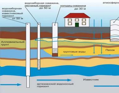
The surface of the earth is covered with air. Like all masses of objects, the mass of air is attracted to the planet Earth under the influence of gravity. Traces of air can exist at a distance of up to 200 miles above the ground. However, 90 percent of the mass of atmospheric air is within 10 miles of the earth's surface.
This mass of air exerts pressure on the surface of the earth, and this is called atmospheric air pressure. Pressure is also measured in atmospheres, where 1 atmosphere = 7 pounds per square inch. The highest point of the earth above sea level is Mount Everest in the Himalayan Range, which separates India and Tibet in China. The height of the earth, measured above sea level, is called the height above sea level or height, and the height of the mountain.
For a rectangular duct determine the so-called. equivalent diameter DL = (2A ст * B ст) / (Aart. + Bart.), m.
Determine the value of the Reynolds simile criterion Re = 64100 * Dart.* v fact. For rectangular shape D L = D st.
Coefficient of friction λ tp = 0.3164 / Re-0.25 for Re≤60000, λtr = 0.1266 / Re-0.167 at Re\u003e 60000.
Therefore, the density of air decreases with altitude above sea level. Since we breathe the same volume of air at any elevation, the mass amount of air and, consequently, the amount of oxygen that we breathe, decreases with increasing elevations. Density reduction also affects the operation of several types of equipment that use or process air. Thus, this equipment is designed for a zero mark, and they need to be reconfigured or re-selected for higher altitudes.
Determination of pressure losses at the bends of air ducts
The pressure of liquids is measured in feet of water, and the pressure of gases is measured in inches of water. Steam is also gas, but the vapor pressure is measured in pounds per square inch. The choice of measuring liquid is associated with convenience and practicality. This can lead to very large or very small values for different situations. Air density also varies with temperature, as shown in the table below. Therefore, outside air in winter is at a higher pressure than air in the room.
Coefficient of local resistance λm depends on their type, quantity and is selected from the directories.
To determine the size of sections on any of the segments of the air distribution system, you need to make an aerodynamic calculation of the air ducts. The indicators obtained with this calculation determine the operability of both the entire designed ventilation system and its individual sections.
This leads to the penetration of outside air through the shell of the building into the space inside the room. Each surface or object on earth has a mass of atmosphere, resting on it. Thus, the absolute weight or pressure exerted by the substance is the weight of the substance on the weight scale plus the weight of the air covering the weight scale. The sum of these two pressures is called absolute pressure. The pressure created by the atmosphere can be ignored for everyday situations, and we can measure pressures and weights above atmospheric pressure.
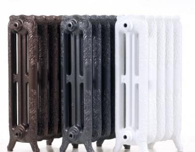
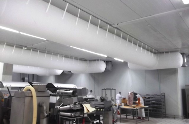
To create comfortable conditions in the kitchen, a separate room or a room as a whole, it is necessary to ensure the correct design of the air distribution system, which consists of many details. An important place among them is the air duct, the quadrature determination of which influences the airflow velocity and the noise of the ventilation system as a whole. Determine these and a number of other indicators will allow aerodynamic calculation of air ducts.
The pressure excluding atmospheric pressure is called the gauge pressure. Absolute pressure can not be ignored in scientific calculations, because atmospheric pressure varies with altitude. Absolute pressure units should be used when considering equations such as gas laws.
It is not possible to measure pressure on the surface of the earth if it is not made with respect to atmospheric pressure. Pressure gauges, piezometers and all pressure gauges show an overpressure, i.e., a pressure above 7 psi. It is assumed that the zero-pound ideal vacuum.
Sequence of execution
It includes several stages, each of them defines a number of indicators, as well as their total values. All elements are formed in the form of tables.
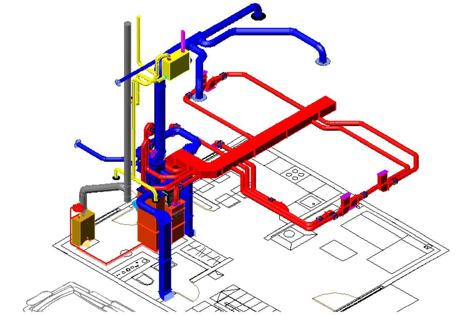
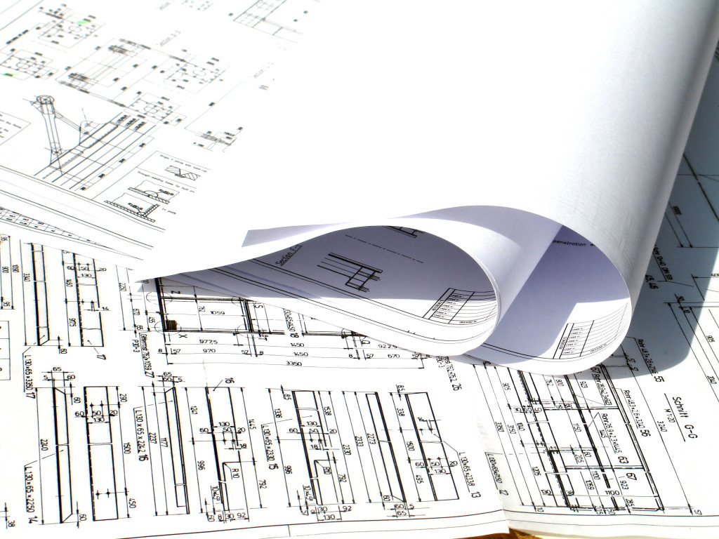
- The axonometric diagram of the air distribution system is developed and prepared for the calculation and selection of air duct sections.
- The aerodynamic resistance is calculated.
- The main line (trunk) and branches are linked.
Stage One
This includes the aerodynamic calculation of mechanical conditioning or ventilation systems, which includes a number of sequential operations. A schematic is shown in the axonometry, which includes ventilation: both supply and exhaust, and is prepared for calculation.
This can not be achieved in practice. The instrument used to measure atmospheric pressure is called a barometer. Mercury is used to measure this pressure, since a tool using a 34-foot-high water column is impractical. The principle of measuring atmospheric pressure is shown in Fig. The tube, which is closed at one end, is first inverted and filled with the liquid used to measure the pressure.
The open end is then closed and inverted, and then immersed in a reservoir containing the same liquid. The liquid in the tube will rise until it reaches a height that has the same equivalent atmosphere pressure at the tank level. The space above the level in the pipe is a vacuum at a pressure of 0. As with temperature measurement, the mercury barometer is not suitable for measuring very high and low pressures and other types of instruments are used.
The dimensions of the area of sections of air ducts are determined depending on their type: round or rectangular.
Formation of the scheme
The scheme is made in the axonometry with a scale of 1: 100. It indicates the points with the ventilation devices located and the consumption of air passing through them.
Channels are usually made of thin lightweight galvanized steel or aluminum, and they are used to distribute air and gases. The shape of the duct can be round, rectangular or oval. Pipes are made of steel, copper, cast iron and other heavy materials, and they are used for the distribution of water and liquids.
Gases and liquids are liquids and differ in their properties of density, kinematic viscosity and heat capacity. Principles of pipe calibration, theory and equations for both channels and pipes are the same. Channels have a size of the first dimension as round, and then equivalent rectangular and oval dimensions are determined for the same pressure as the circular channel.
Here it is necessary to determine the main line - the main line from which all operations are carried out. It is a chain of consecutively connected segments, with the greatest load and maximum length.
When building a highway, it is necessary to pay attention to what system is designed: supply or exhaust.
These equations use computer programs to design pipes and channels. However, the diagrams generated by the equations are used to manually calibrate pipes and channels. In the case of rectangular ducts, tables are provided for converting circular ducts into equivalent rectangular ducts.
General principles of pipe calibration are described in Chapter 34, page. The Darcy-Weisbach and Colebroke-White equations are used to calculate the pressure drop in the pipe section due to fluid friction. The Darcy-Weisbach equation. Where ε = absolute roughness of the inner wall of the pipe.
Supply air
Here the line of calculation is built from the most remote air distributor with the greatest consumption. It passes through such supply elements as air ducts and ventilation plant up to the place where air intake takes place. If the system is to serve several floors, then the air distributor is placed on the latter.
For a complete rough flow, the value of the Reynolds number is large, and the last term in Eq. 20 can be neglected. Equation 21 can be used in its place. As the Reynolds number increases, the values from equation 20 approach values that would have been obtained by applying equation 21 directly for a completely coarse stream. The pipe dimensions and the size of each pipe section depend on your criteria. Criteria can be based on the limits of pressure loss per 100 feet, maximum speed or maximum flow.
This is done for each standard pipe size, starting with the smallest size and continuing until a size matching the criteria is found. When the maximum pipe size limit is reached, you must use your engineering solution to decide whether to proceed.
Extraction
A line is constructed from the most remote exhaust device, which consumes the air flow as much as possible, through the main line, before installing the exhaust and further to the shaft through which the air is vented.
If ventilation is planned for several levels and the exhaust system is located on the roof or attic, the calculation line must begin with the air distribution unit of the lowest floor or basement, which also enters the system. If the extractor unit is located in the basement, then from the air distribution unit of the last floor.
Fig .: Properties of liquids
Maintain the calibration criteria and increase the pipe size above the maximum limit or maintain the pipe size constraint and calculate new criteria for this size.
Properties of pipe materials used in buildings
You can choose one of two options for determining the temperature of the liquid in each section of the pipe. In the first variant, you can take the average flow and return temperature for all feed and return sections. This data is used to calculate fluid properties.In the case of uninsulated pipes and high-temperature steam and hot water, the feed temperature at each terminal must be calculated. This is done by calculating the input and output temperatures of each power section, starting with the initial temperature of the first section. It is necessary to determine the first section. In the case of liquids, the first section is the cross section behind the pumping station.
The entire calculation line is divided into segments, each of them is a section of the duct with the following characteristics:
- single-section air duct;
- from one material;
- with a constant intake of air.
The next step is the numbering of segments. It starts with the most remote exhaust or air distributor, each assigned a separate number. The main direction - the highway is marked by a thick line.
The inlet temperature in any power section is the outlet temperature in the upper section. You can reset the temperature of the outgoing section for sections having the main equipment. To calculate heat losses and heat losses and heat heat, the following equations are used.
Equation 12 is based on the heat flux. The average temperature of the section is the average value of the temperature entering and exiting the section. Since the tempering temperature is unknown, the average temperature is calculated iteratively. The temperature of the liquid flowing through the pipe section is obtained from the equation. The procedure for determining the temperature changes of the steam is described in the Steam Line.
Further, on the basis of the axonometric scheme, for each segment, its length is determined taking into account the scale and air consumption. The latter is the sum of all values of the consumed airflow flowing through the branches that are adjacent to the main. The value of the indicator, which is obtained as a result of sequential summation, should gradually increase.
Frictional losses for non-circular air ducts
All calculations of friction losses are based on an equivalent hydraulic diameter. With the same length of round and rectangular channels, constant flow in each channel and equal flow resistance in both circular and rectangular channels, the equivalent circle of a rectangular channel is calculated by the formula.
The average velocity in a rectangular and oval channel will be less than its circular equivalent. For oval channels, the corresponding equations. For both rectangular and oval channels, the length of the sides is initially determined by the target aspect ratio. If the resulting dimensions do not correspond to the minimum and maximum permissible limits, the dimensions are recalculated without using the target aspect ratio.
Determination of the dimensional values of the duct sections
It is based on such indicators as:
- air consumption on the segment;
- the recommended recommended values for the speed of the air flow are: on the roads - 6 m / s, in the mines where the air intake is 5 m / s.
The preliminary dimensional dimension of the duct is calculated on the segment, which is reduced to the nearest standard one. If a rectangular duct is selected, the values are selected based on the dimensions of the sides, the ratio between which is no more than 1 to 3.
Stage Two
Here, aerodynamic resistance values are calculated. After selecting the standard sections of the air ducts, the speed of the air flow in the system is specified.
Calculation of frictional pressure loss
The next step is to determine the specific frictional pressure loss based on tabular data or nomograms. In some cases, a calculator may be useful for determining indicators on the basis of a formula that makes it possible to calculate with an error of 0.5 percent. To calculate the total value of the indicator characterizing the pressure loss throughout the section, its specific index must be multiplied by the length. At this stage, the correction factor for roughness should also be taken into account. It depends on the absolute roughness of this or that duct material, as well as speed.
Calculation of the dynamic pressure on the segment
Here, an index is determined that characterizes the dynamic pressure at each section based on the values:
- airflow velocity in the system;
- density of the air mass under standard conditions, which is 1.2 kg / m3.
Determination of the values of local resistances in sections
They can be calculated on the basis of the coefficients of local resistance. The obtained values are summarized in tabular form, which includes data from all areas, not only straight lines, but also several shaped parts. The name of each element is entered in the table, the same values and characteristics are indicated there, along which the coefficient of local resistance is determined. These indicators can be found in the relevant reference materials for the selection of equipment for ventilation plants.
In the presence of a large number of elements in the system or in the absence of certain values of the coefficients, a program is used that allows you to quickly perform cumbersome operations and optimize the calculation as a whole. The total resistance is defined as the sum of the coefficients of all elements of the segment.
Calculation of pressure losses at local resistances
After calculating the final total value of the indicator, proceed to calculate the pressure loss in the analyzed areas. After calculating all segments of the main line, the numbers obtained are summed and the total value of the resistance of the ventilation system is determined.
Stage three: linking the branches
When all necessary calculations have been carried out, it is necessary to link several branches. If the system serves one level, then the branches that do not enter the main line are linked. The calculation is carried out in the same order as for the main line. The results are entered in the table. In multi-storey buildings, linkage is used for linking at intermediate levels.
Linkage criteria
Here, the values of the sum of losses are compared: the pressure across the segments to be connected with the parallel line connected. It is necessary that the deviation is not more than 10 percent. If it is determined that the discrepancy is greater, then the linkage can be carried out:
- by selecting the appropriate sectional dimensions of the air ducts;
- using the installation of diaphragms on the branches or throttling valves.
Sometimes for such calculations only a calculator and a couple of directories are needed. If the aerodynamic calculation of ventilation of large buildings or industrial premises is required, then a corresponding program will be needed. It will allow you to quickly determine the size of sections, the loss of pressure both on individual segments, and in the entire system as a whole.
http://www.youtube.com/watch?v=v6stIpWGDow Design of ventilation systems. (http://www.youtube.com/watch?v=v6stIpWGDow)