Losses in the cable at full load. Loss of voltage in the wires
Loss of voltage in the wires of the line. The transmission of electrical energy from the source I (Figure 33) to the receiver 2 takes place via the wires that form the electric line. When transferring energy, a voltage loss occurs in the wires of the line
? U л = IR л (36)
where R l, is the resistance of the line wires.
As a result, the voltage U 2 at the end of the electrical line is less than the voltage U 1 at the beginning of the line. The voltage loss in the wires of the line is not constant, it varies depending on the load current from zero (at I = 0) to the maximum value (at maximum load). In addition, it depends on the resistance R l of the wires of the line,
ie, on their specific conductivity ?, the cross-sectional area s, and the line length ll.
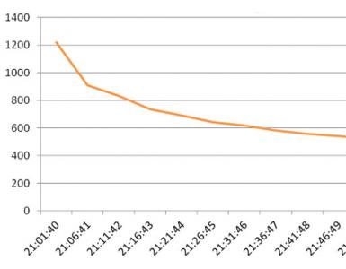
On electrified railways, one of the wires connecting the power source - the traction substation with the electric locomotive user - is the contact wire, and the other is the rails. Therefore, under the loss of voltage in the wires? U This case is understood as the total loss of voltage in the contact network and rails. The loss of voltage in the line increases as the electric locomotive is removed from the traction substation, and accordingly the voltage on its current collector decreases.
The loss of power in the line and its efficiency. When passing through the current line I, a part of the power P 1 coming from the source is lost in the line causing heating of the wires, these power losses
? P n = I 2 R n = I? U l (37)
Consequently, the receiver of electrical energy included at the end of the line will receive less power
P 2 = P 1 -? P l (38)
As the current I increases, the power losses in the wires of the line increase, and the efficiency decreases. line and voltage U 2, applied to the load.
Practically electrical energy is transmitted by wire at? = 0,9-0,95, while the line resistance of the line is 5-10% of the load resistance and the energy loss in them does not exceed 5-10% of the transmitted power.
Let us now consider how the power losses in the line and its efficiency depend on the voltage U 2 at which electric power is transmitted. Power loss in line wires
? P l = I 2 R liters= P 2 2 / U 2 2 * 2?l l / s l (39)
Consequently, the greater the transmitted power P 2 and the distance l l to which it is transmitted, the greater the loss of power and energy in the wires; The larger the cross-sectional area of the wires S l and the voltage U 2 in the transmission line, the smaller these losses, therefore it is more advantageous to transmit electric energy at higher voltages.
Principles of the calculation of wires. For the correct operation of the electric energy receivers, it is very important that the voltage applied to them be kept as constant as possible and equal to their rated voltage. Lowering the voltage causes a significant weakening of the glow of electric lamps and a deterioration in the operating mode of electric motors, and an increase in comparison with the nominal - a reduction in the service life of lamps and electric machines.
Electrical wires are usually calculated from the permissible loss of voltage. The loss of voltage in the wires is allowed to be small compared to the voltage of the network in order to save electrical energy and to provide a small voltage fluctuation at the receivers. In electrical networks for various purposes, the permissible voltage losses are approximately 2-6%. Based on these conditions, the calculation of electric wires is carried out, that is, the selection of the area S of their cross section. It is chosen such that at maximum load, the voltage loss from the power source to the outermost receiver does not exceed 2-6% of the nominal voltage. In electric traction, the selection of the area of the contact wires is also made from the condition that the voltage of U 2 acting on the current collector of the electric locomotive is sufficient for the normal operation of the electric locomotive machines.
Relative loss of voltage in the line,%,
? = (? U l / U 2) of 100%.
Replacing in this formula? U = IR = I2? L / S l and I = P 2 / U 2, we find that the cross section of the wires of the line
S n = (200? /?) (P 2 i l /U 2 2) (39 & apos;)
It follows from (39 '):
1) the greater the transmitted power and the more it is transmitted, the greater the cross-section of the line wires;
2) an increase in the voltage in the line allows a significant
degree reduce the section of the wires of the line and reduce the power loss in it.
When transmitting electrical energy over a long distance, the benefits obtained by increasing the voltage are widely used. The more power is required to transmit and the greater the distance to which it is transmitted, the higher the voltage is used in the transmission lines. For example, when power is transferred from powerful power plants (Kuibyshev, Volgograd and others), a voltage of 500-750 kV is used for a distance of 800-1000 km; when the energy is transferred to a distance of 100-200 km-110-220 kV; when a relatively small amount of energy is transmitted over a distance of several kilometers or tens of kilometers-35 kV. In electrical installations of low power with the arrangement of electrical receivers near sources
Voltage 110, 220, 440 V (with constant
current) and 127, 220, 380, 660 V (with alternating current).
With electric traction, the higher the voltage in the contact wire, the smaller the cross-sectional area it will have and the more distant the power sources of the contact network (traction substations) can be located. For example, for the supply of electric power, a tram, whose engines have a relatively small capacity, and a contact network - a small length, use a voltage of 600 V, and on the mainline railways electrified on a direct current (where powerful locomotives are operated), 3300 V. Electrification of iron roads on alternating current makes it possible to raise the voltage in the contact network to 27500 V, which allows to significantly reduce the cross-sectional area of the wires of the contact network and to increase the distance between traction to Recently, work is underway to further increase the voltage in the contact network on alternating current roads up to 2 * 25 kV.
Loss of line voltage
To understand what is voltage loss, consider the voltage vector diagram of a three-phase AC line (Figure 1) with one load at the end of the line (I).
Suppose that the current vector is decomposed into the components I a and I p. In Fig. 2, the phase voltage vectors at the end of the line U 3f and current I, lagging behind it in phase by an angle φ2, are plotted on a scale.
To obtain the stress vector at the beginning of the line, U1 φ follows the triangle of voltage drops in the line (abc) at the end of the vector U 2φ. For this, the vector ab, equal to the product of the current by the active resistance of the line (I R), is parallel to the current, and the vector bc, equal to the product of the current by the inductive resistance of the line (I X), is perpendicular to the current vector. Under these conditions, the straight line connecting points O and c corresponds to the magnitude and position in space of the stress vector at the beginning of the line (U1 φ) relative to the voltage vector at the end of the line (U2 φ). Combining the ends of the vectors U1 φ and U2 φ, we obtain voltage drop vector at full line resistance ac = IZ.
Fig. 1. Scheme with one load at the end of the line
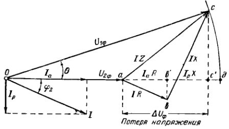
Fig. 2. Vector voltage diagram for a single-load line. Loss of voltage in the line.
We agreed to call loss of tension algebraic difference of phase voltages at the beginning and end of the line, i.e., the segment ad or almost equal to it the segment ac ".
The vector diagram and the relations derived from it show that loss of voltage depends on the network parameters, as well as on the active and reactive components of the current or load power.
When calculating the value of the voltage loss in the network, the active resistance must always be taken into account, and the inductive resistance can be neglected in lighting networks and in networks made with wire cross-sections up to 6 mm2 and cables up to 35 mm2.
Determination of line voltage loss
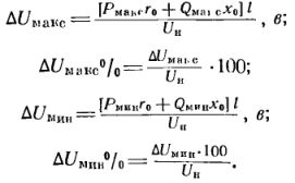
The loss of voltage for a three-phase system is usually denoted for linear quantities by the formula
where l is the length of the corresponding section of the network, km.
If we replace the current by the power, the formula takes the form:
![]()
where P - active power, Q - reactive power, kVAr; l is the length of the section, km; Un - the rated voltage of the network, kV.
Changing the line voltage
Allowable voltage loss
For each power receiver, certain voltage drop. For example, asynchronous motors under normal conditions allow a voltage deviation of ± 5%. This means that if the rated voltage of this motor is 380 V, then the voltage U "add = 1.05 U n = 380 x 1.05 = 399 V and U" add = 0.95 U n = 380 x 0.95 = 361 B should be considered its maximum permissible voltage. Naturally, all the intermediate voltages between the values of 361 and 399 V will also satisfy the consumer and will form a certain zone, which can be called the zone of desired voltages.
Since during the operation of the enterprise there is a constant change in the load (power or current flowing through the wires at a given time of day), the network will also have various voltage losses varying from the largest values corresponding to the maximum load regime dUma x to the smallest dUmin , corresponding to the minimum load of the consumer.
To calculate the magnitude of these voltage losses, use the formula:
It follows from the stress vector diagram (Figure 2) that the actual voltage at the receiver U2φ can be obtained if the voltage at the beginning of the line U1 φ is subtracted from the value of dUφ, or, passing to linear, ie, phase-to-phase voltages, we obtain U2 = U1 - dU
Calculation of voltage losses
Example. The consumer, consisting of asynchronous motors, is connected to the buses of the transformer substation of the enterprise, on which a constant voltage U1 = 400 V is maintained during the day.
The greatest load of the consumer was noted at 11 am, with the voltage loss dUmax = 57 V, or dUmax% = 15%. The lowest load of the consumer corresponds to the lunch break, with dUmin - 15.2 V, or dUmin% = 4%.
It is necessary to determine the actual voltage of the consumer in the modes of the greatest and smallest loads and check whether it lies in the zone of the desired stresses.
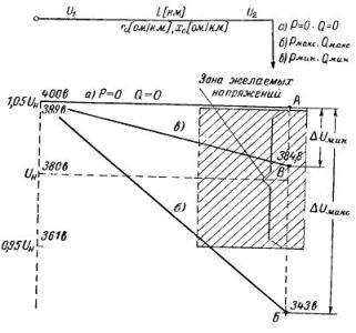
Fig. 3. Potential diagram for a single-load line for determining the voltage loss
Decision. We determine the actual values of the stresses:
U2 max = U1 - dUmax = 400 - 57 = 343 V
U2min = U1 - dUmin = 400 - 15.2 = 384.8 V
Desired voltages for asynchronous motors with UH = 380 V must satisfy the condition:
399 ≥ U2 yellow ≥ 361
Substituting into the inequality the calculated values of the stresses, we see that for the high-load regime the ratio 399\u003e 343\u003e 361 is not satisfied, and for the smallest loads 399\u003e 384.8\u003e 361 is satisfied.
Conclusion. In the mode of the greatest loads, the voltage loss is so great that the consumer's voltage goes beyond the desired voltage range (decreases) and does not satisfy the consumer.
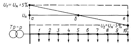
This example can be illustrated graphically by a potential diagram in Fig. 3. In the absence of current, the consumer's voltage will be numerically equal to the voltage on the supply rails. Since the voltage loss is proportional to the length of the supply line, the voltage in the presence of the load varies along the line along the slope from the value U1 = 400 V to the value U2max = 343 V and the value U2min = 384.8 V.
As can be seen from the diagram, the voltage in the mode of the greatest load has left the zone of the desired stresses (point B of the graph).
Thus, even with a constant value of the voltage on the bus bars of the power transformer, sudden changes in load can create an unacceptable amount of voltage in the receiver.
In addition, it may turn out that with changes in the load in the network from the greatest load in the daytime to the lowest load at night, the energy system itself will not be able to provide the proper voltage value at the transformer terminals. In both these cases, it is necessary to resort to means of local, mainly, stepwise voltage variation.
As can be seen from the preceding discussion, the stress U and at the beginning of the line (at the source terminals), the emf is less than the voltage drop in the energy source ( U and = E and - Ir in and), and the stress U p at the terminals of the receiver is less U and by the amount of voltage drop in the line.
Reducing the voltage during the transmission of electricity through the wires is called a change or loss of voltage in the line and for the DC circuits is equal to the voltage drop on the corresponding section of the circuit.
In practice, the deviation of the voltage from the nominal value under load fluctuations is usually calculated. The deviation of the voltage towards the reduction is limited by the fact that when the voltage decreases, the output characteristics of the electric power consumers deteriorate significantly, the light flux of the incandescent lamp decreases sharply, the electric motors require currents exceeding the nominal ones.
If the voltage is deflected in the direction of increasing the incandescent lamp, for example, they can quickly fail, and the motors will operate under unacceptable conditions.
Therefore, voltage deviations in industrial networks have strict tolerances:
In the direction of 2.5 ... 5% decrease;
In the direction of an increase of 5%;
Onboard networks:
The constant current (+ 5 ... - 10%) = 28 V;
Alternating current (+ 2 ... - 3%) ~ 200 V;
In the three-phase generators of the latest generation, ± 0.5%.
Calculation of the line for voltage deviations for the greatest and smallest loads is as follows:
Determination of the cross-section of the wires (an inverse problem can be posed: the determination of the losses and the deviation of the voltage for the line at given sections of the wires and loads);
Selecting or checking the section of the wires of the line without overheating when the current flows (an inverse problem can also be set here: checking the available wires of a certain section for the absence of overheating).
The voltage at the beginning of the two-wire line U and (Figure 1.11), which connects the energy source to any receiver (for example, an electric motor, a group of lamps, etc., denoted by conditional load r n), is determined from the formula: U p = U AND - 2I R l ,
from here U and = U p + 2I R l (1.20),
where U p - voltage at the end of the line (at the terminals of the receiver);
R l - resistance of each line wire.
The difference in voltages at the beginning and end of the line U and and U p is called a voltage loss in the line and is denoted by ΔU l :
∆U l = U and - U p = 2I R l (1.21)
From physics it is known that R l = (1.22),
consequently, ΔU l = I (1.23),
where L is the length of one wire in a line, m;
S - cross-sectional area of wires, mm 2;
- Specific resistance of conductor materials, Ohm * mm 2 / m; (in the SI system, the unit of resistivity is Om * m, 10mm = 10 6 Ohm * mm 2 / m).
Relative loss of voltage in the line, i.e. loss of voltage in percent is defined as
![]() (1.24)
(1.24)
Knowing the current I and the maximum allowable voltage loss ΔU Ldop , you can find the required cross-section of wires ΔU Ldop =, from here
The conductor cross-section calculated according to this formula is rounded to the nearest standard (upwards).
Power loss in the line:
ΔP л = ΔU л I = 2I 2 R Л (1.26)
With the loss of voltage and power in the line, the efficiency of the line η is closely related, defined as the ratio of the power P n given to the receiver to the power P received from the power source and:
or in percentages:
The less the line voltage loss, the greater the efficiency of the line.
Instead of the efficiency of the line, the value (ratio) of the relative power loss in it is often considered.
that is, the relative power loss in a two-wire DC line is equal to the relative loss of voltage in it.
From the expression for ө we obtain by multiplying the numerator and the denominator by U and
From this it is clear that when a given power is transmitted, the voltage losses in the wires are inversely proportional to the square of the voltage of the power source.
As can be seen from the last expression (1.30), with an increase in the length of the wire to transmit the required power for given losses and an acceptable cross-section of the wires, it is necessary to increase the voltages U and the energy source. In this case, the relative magnitude of the voltage loss will decrease inversely proportional to the square of the voltage. Therefore, high-power transmission over long distances is carried out via high-voltage lines.