What is the dependency characteristic of the fuse. Choice of fuses
The overhaul period for fuses is not defined. The fuses are usually repaired simultaneously with the rest of the substation equipment and when defects are identified that require their removal. Scheduled repairs begin with cleaning of insulators with contacts and a cartridge from dust and dirt. Then, by visual inspection, the integrity of the porcelain insulation and the reinforcement of brass caps at the ends of the cartridges are checked. The cracked supporting insulators and cartridges are replaced, and the broken reinforcement is restored. Also check the contact density of the contact surfaces of the caps or knives with spring contacts. If necessary, bend the contact clips and iron bracket. If the copper clamps due to overheating lost elasticity, the contacts are replaced. Clicking on the cylindrical pointer of the PKT fuse, they check the ease of its movement inside the cartridge. If necessary, replace the fuse. In addition, check the quality of fuse connections with busbars. A bad contact causes the cartridge's jaws and fuse to reach an allowable temperature and may cause a fuse to malfunction. During the repair process, it is necessary to check the compliance of the rated voltage and the fuse current with the voltage and maximum allowable overload current of the protected installation or network section, otherwise there may be erroneous disconnections or damage to the protected installation. Recharging fuses with quartz filler is carried out in repair shops in accordance with factory instructions. When repairing PC fuses, porcelain and reinforcement should be inspected at the ends of the cartridge and brass caps. Damaged reinforcement restore. Check the tightness of the contact surfaces of brass caps or knives with a spring-fixed contact. Contact density is achieved by bending the contact clips. If the contact from overheating has lost its elasticity, it is replaced. The pickup indicator consists of a metal roof with a sleeve inside which a coil spring is placed. One end is fixed to the bottom of the sleeve, the second - to the head of the pointer and provided with a small hook, which hook on the inside of the pointer wire, which, burning out, throws out the head. Check the contact connections with busbars. The design of the fuse with quartz filling provides multiple recharging, which is performed by qualified personnel in the repair shops according to factory instructions. The integrity of the fuse link is checked with a test lamp. The completeness of the quartz sand backfill is checked by gentle shaking. Old sand is left in exceptional cases if it is not sintered and not damp (humidity less than 0.05%). The size of the grains of sand should be 0.5-1 mm. The caps are fixed on cement mortar (grade 400-500) to prevent moisture from entering the cartridge.
4.4 Conditions for the selection of fuses.
a) Rated voltage. The rated voltage of the fuses and their fusible inserts U VS.NOM regardless of the place of installation should be chosen equal to the rated voltage of the network.
b) Extremely switchable current. Maximum switchable current fuse-link I Sun. must be equal to or greater than the maximum rated short-circuit current I Ksmax. running through a circuit protected by a fuse. If this condition is not met, the arc that occurs when the fuse link is blown may not go out, and the fuse as a result of it long burning will collapse. Thus, the second condition is
c) Rated current. The rated current of the fuse-link should be minimal in all cases. In this case, the fusible insert should not burn out while passing through it the maximum continuous load current I m.max. With a variable load, the fusible insert should not also burn out during short-term overloads when a current in excess of the maximum continuous load current passes in the protected network. Short-term overloads can be caused by starting or self-starting of electric motors, technological overloads of mechanisms rotated by electric motors, and other reasons. Blown fuses in these cases is unacceptable, since overloads after a short time (2-10 s) are eliminated and the normal mode is restored. To meet this condition, the rated current of the fuse-link is chosen so that when the current of the overload I per. burnout time was longer overload time.
This means that in case of damage, for example, one of the electric motors (at point K in Fig. 2-3), only the P 3 fuse should blow and P 1 and P 2 fuses should not blow, and also the relay protection relay should not operate installed on the switch. In other words, for the correct repair of damages, all successively installed fuses and relay protection must be selective.To verify the selectivity, it is necessary to compare the characteristics of fuse-links in the entire range of currents possible both in case of overloads and short circuits.
The protective characteristic of the fuse can be specified by the manufacturer in two forms: either as a total off time equal to the sum of the melting times of the insert and the arc, or separately as the melting time and the arc time. Strictly speaking, when checking the selectivity of two series-connected fuses, the melting time of the insert, installed closer to the power source, should be compared with the full time of disconnection of the insert, installed further from the power source. In practice, the same characteristics of the total off time are usually used, since the arc burning time is small, and the melting and off time spreads overlap the inaccuracy of the calculations.
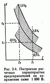
When performing calculations, possible variation of characteristics should be taken into account due to deviation of the insert dimensions, the state of the contacts and the surfaces of the inserts, ambient temperature and other factors. The spread of the protective characteristics of fuses for voltages below 1000 V reaches 50%. Such a spread should be taken when checking the selectivity of fuse-links.
To check the selectivity, the factory characteristics of the fuse-links are rearranged into the calculated ones, as shown in fig. 2-4. The possible tripping times at certain currents are within the area bounded by the constructed curves. In accordance with a possible error of ± 50%, the selectivity between two adjacent fuses is ensured if the time determined for the factory characteristic to blow the larger fuse at least 3 times longer than the burnout time for the characteristic of the smaller fuse.
|
|
When analyzing the characteristics of single-type fuses, selectivity should be checked at the maximum three-phase short-circuit current. If the selectivity at this current is ensured, it will be ensured at all lower values of the currents.
For fuses of different types, selectivity should be checked over the entire range of currents - from a three-phase short-circuit current at the place of installation of the long-range fuse to the reference current of the inserts.
If the protective characteristics of the fuse-links are unknown, a method of matching the characteristics of the fuses is recommended, based on a comparison of the cross-sectional areas of the fuse-links with the material from which they are made.
To verify the selectivity of this method, it is necessary to know the type, material and cross-sectional area of fuse-links, between which matching is made. If the cross-sectional area of the fuse-link 1, located closer to the power source, s 1, and the insert 2, farther from the power source, s 2, then the ratio of these areas is determined
![]()
The value obtained is compared with the data table. 2-1. If a is equal to or greater than the value given in the table, then the selectivity between the considered fuses is ensured.
|
|
For the selective action of series-installed high-voltage PC-type inserts, it is necessary that their rated currents differ by at least one scale level.
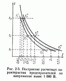
When checking the selectivity of inserts for their protective characteristics in a network with a voltage higher than 1000 V, it should be borne in mind that their variation is regulated as follows: for any off time, the deviations in the current value should not exceed 20%. The construction of design characteristics for such fuses is shown in Fig. 2-5.
When checking the selectivity of fuses installed on different sides of a transformer, it should be taken into account that currents of different size will flow through the fuses.
where - the transformation ratio of the transformer. e) Selection of fuse-links in secondary circuits. The rated current of a fuse-link installed in operating current circuits or in secondary circuits of voltage transformers is adopted according to the following expression:
where I H is the maximum load current. The current I H can be determined by direct measurement in the mode when all relays and devices are turned on, which can be simultaneously powered from given voltage or operating current circuits. The magnitude of the maximum load current can also be determined by calculating the known consumption values of each relay and device. For example, for a voltage transformer, to the terminals of the secondary winding of which, connected to a star, relays and devices for phase and phase-to-phase voltages are connected, the maximum load current can be determined with a certain margin by the following expression [L. 86]:
where R f - the consumption of the load connected to the phase voltage, V * A; - respectively, the largest and smallest consumption of the load connected between the two phases, V * A; U f - phase voltage, V. For reliable combustion of the insert in case of a short circuit, the ratio of the short circuit current to its rated current should not be less than 5-10. Fuses in the circuits of the electromagnets turn on to protect the latter from the long passage of current. The rated current of these inserts is assumed to be 0.3-0.4 of the maximum current flowing in the switching circuit.
Fuses choose according to the rated current of the fuse-link I SunThe following conditions must be met:
1. the rated current of the fuse link must be greater than or equal to
the maximum rated current of the circuit in operation, i.e.
I sun ≥ I p
2. fusible insert should not burn out during the launch of the most powerful
electric motor connected to this circuit.
I sun =
where Peak i- peak current, A. Define peak current
a) for one asynchronous motor Peak i = I p = k p · I n
where k p -starting current rate
b) for a multi-motor drive, as well as a group of EP
Peak i = I p. Max + k about ·
where I p.max- the largest starting current of the receiver
k about -coefficient of simultaneity (in the absence of
data k o =1)
- the sum of the calculated currents of the remaining ES of the group
c) for RP or highway
Peak i =
where I max - the maximum rated current of the RP or highway
k andand I m.max -utilization rate and
rated current of the VC group having
highest starting current
K P - coefficient of short-term insertion overload
K P =2.5 with easy start (no load)
K P = 1.6 ... 2.0 with a heavy start (with load)
K P = 2.75 ... 3 when protected by group fuses
lighting network with incandescent bulbs
\u003e 500 W
3. the rated current of the fuse-link must be less than or equal to
three times the allowable current of the wire (calculated by heating).
I in< 3I доп. пр.
2.2.5.3 Automatic Machines(Bring the machine)
Circuit breakers or circuit breakers.
used to protect network elements from the currents k.z. and as operational switching devices. Automatic control can be manual and remote. Automatic machines are produced in one-, two- and three-pole versions for direct and alternating current networks.
The main elements of the machines that perform their protective functions under abnormal conditions in the circuit are the releases, when activated, the machine shuts down instantly or with a time delay. The machine may have one or more releases.
By the principle of operation, the releases are divided into electromagnetic (M), thermal or thermo-bimetallic (T) and combined (MT). Usually, circuit breakers have built-in trip units.
There are overcurrent releases that operate at a current greater than the pick-up current setting; undervoltage releases, which are triggered when the voltage on the coil becomes less than the set point and the tripping devices are independent, which are triggered without a time delay when voltage is applied to their coil.
For short-circuit protection, electromagnetic releases of instantaneous action or with a time delay are used to ensure the selectivity of action. Simultaneous protection of the network against short-circuit and overload is achieved through the use of combined trip units consisting of two elements - for protection against short-circuit and overloads.
The machine is characterized by the following indicators:
Rated voltage U n
Rated current of the machine I N.A.- maximum continuous current of it
main contacts
Automatic current I sr. -the lowest current at which the machine
disconnects the circuit
Trip Current Limit I pr.a -greatest current that can
turn off automatically
Rated current release I nr- maximum continuous current, at
which the trip does not work
Tripping current I y -the lowest tripping current
on which he is configured
The instantaneous setting current of the electromagnetic release
I am = I ohcalled cut-off current
Automata are divided into non-selective with a response time of 0.02 ... 0.1 s, selective with adjustable time delay and current-limiting with a response time of not more than 0.005 s
Nowadays, automatic switches (AB) of both foreign and domestic manufacturers are becoming more and more popular, this is primarily due to the fact that AB has no flaws in the fuses. But in spite of all its shortcomings, the fuses are still actively used, since this is the cheapest option to protect the connection.
For example, in our company, if the customer does not object, to protect motors up to 100 kW, a fuse switch is used, since short circuits are not so common, a fuse is a very good solution to protect the connection.
In this regard, in this article I will tell you how to choose the right fuses with fuses in accordance with the EMP and other reference books, so that your fuses are only activated during abnormal operating conditions of electrical consumers.
When choosing a fuse, the following conditions must be met:
The rated voltage of the fuse must correspond to the mains voltage:
Unom = Unom. (1)
The rated current of the fuse trip must be not less than the maximum short-circuit current. at the place of installation:
Inom.tkl\u003e Imax.kz (2)
Conditions for the selection of fusible inserts:
The current of the fuse-link must be greater than the maximum current of the protected connection:
IT \u003e Irabmaks. (3)
When protecting a single induction motor, the fuse-insert current is selected taking into account the motor start:
IT \u003e Ipusk.dv / k (4)
where: k - coefficient, is taken equal to 2.5 according to [Л1. with. 124.125], which corresponds to PUE, clause 5.3.56, for electric motors with a short-circuited rotor with a small frequency of starts and easy starting conditions (tn = 2-2.5 sec.). Usually this coefficient is adopted for the motors of fans, pumps, main drives of metal-cutting machines and mechanisms with the same mode of operation.
For engines with severe starting conditions (tп\u003e 10-20 sec.), For example, for engines of agitators, crushers, centrifuges, ball mills, etc. And also for engines with a high frequency of inclusions, i.e. for engines of cranes and other intermittent mechanisms, the coefficient k is assumed to be 1.6 - 2.
For motors with a phase-rotor, the coefficient k is taken equal to 0.8 - 1.
When choosing a fuse-in current according to the condition (4), it should be taken into account that the protective properties of the insert deteriorate over time, because of this there is a probability of false combustion of the fuse-insert when the motors start. As a result, the engine may not start at all, or work on 2 phases, which leads to overheating of the engine.
And if overload protection is not provided, the engine may fail.
The solution to this problem is the choice of a larger current of the fuse-link than by condition (4), if this is permissible by sensitivity to short-circuit currents.
When protecting the assembly, the current of the fuse-link is selected according to three conditions:
The most long-term current:

At full load assembly and start-up of the most powerful engine:

When self-starting engines:

Where:
k - coefficient taking into account the conditions of the engine start;
The sum of the maximum operating currents of electrical receivers, except for the engine with the highest starting current I start-up max .;
To check the reliable operation of the fuse at the end of the protected line, you need to perform on the frequency of the current kz and take into account the tripping time.
In the reference literature, you can meet such a statement that for reliable and fast melting of the fuse-link, it is required that the short-circuit current ratio Ikz to the rated current of the fuse-link InS should be provided at the end of the protected line. .
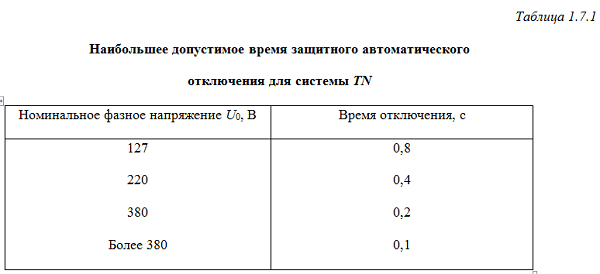
This condition was taken, from clause 1986 of the 1986 model, clause 1.7.79 (for non-explosive environments: kkz = Iкз / Iн.сс (kкз\u003e 3), this clause in the 7th edition of the PUE was changed, and now it is necessary to take into account the off time in the TN system, according to table 1.7.1.
For an explosive environment, according to PUE 7th edition clause 7.3.139, the condition of current ratio kz should be fulfilled: kкз = Iкз / Iн.сс (kкз\u003e 4). This paragraph has remained unchanged when compared with the OIE 1986, which is very strange, considering that paragraph 1.7.79 has changed.

If you do not know the values of the starting currents of the motor, then in order of exceptions, you can select the rated currents of fuse-links for motors with a power up to 100 kW and a starting frequency of no more than 10-15 per hour as follows [L2. with. 15]:
- at Un.seti = 500 V In.vs = 4.5 * PH;
- when Un.seti = 380 V In.vs = 6 * PH;
- when Un.seti = 220 V In.vs = 10.5 * PH.
After you have chosen a fuse, you need to perform a selectivity check (selectivity) of fuses in series with each other, taking into account the protective characteristics.
This means that in the event of a short circuit, only the melting insert and the fuse that is closest to the point of damage should blow. As practice shows, to ensure selectivity between two series-connected fuses. It is necessary that the fuses differ by two steps on the scale of rated currents. In this case, the inserts must have the same protective characteristicsso you need to choose one type of fuses.
That's basically all you need to know about the choice. fusesIf this information is not enough for you, I recommend reading the literature that I used when writing this article. In the next article, I will cite fuse selection examples for various electrical receivers.
Literature:
1. A.V. Belyaev. Selection of equipment, protection and cables in 0.4 kV networks. Energoatomizdat, Leningrad Branch, 1988 Issue 617.
2. E.N. Zimin Protection of asynchronous motors up to 500 V. 1967
3. Rules for electrical installations (PUE). Seventh edition. 2008
Side 37 of 54
16.5. SELECTION OF FUSES
a) Selection according to the conditions of long-term operation and start-up. In the process of long-term operation, the temperature of the fuse must not exceed the permissible values. In this case, the stability of the time-current characteristics of the fuse is ensured. To fulfill this requirement, it is necessary that the cartridge and the fuse-link are selected for a rated current equal to or slightly larger than the rated current of the protected installation.
The fuse must not shut down the installation in case of overloads that are operational. Thus, the starting current of an asynchronous motor with a squirrel-cage rotor can reach 7 / HOhm. As acceleration starts, the starting current drops to a value equal to the rated motor current. The duration of the start depends on the nature of the load. For example, for the drive of metal-cutting machines with a relatively small inertia of the mechanism, the acceleration time of the engine is 1 s. The process of acceleration of the centrifuge is much slower due to the large inertia of the mechanism, and the duration of the start can be up to 10 s or more. The fuse should not burn out when exposed to inrush currents, and in fusible inserts aging should not occur under the influence of these currents. It was established experimentally that aging of the fuse-link does not occur at currents equal to half the melting current. According to fig. 16.7 insert fuse PN-2 at a time of 1 s melts at a current equal to 5 / Nom- Due to manufacturing tolerances, the time-current characteristic has a variation (dashed curves). If the start lasts for 1 s, then the average starting current for this period should be no more than 0.5 melting current of the insert during the same time. Thus, the starting current / n is related to the insertion current by the ratio / n = 0.5 / Pl = 0.5-5 / v, nom and, therefore,
^ v.nom - 0\u003e 4 / p,
those. The rated current of the insert is selected based on the starting load current.
For severe starting conditions, when the engine slowly turns around (centrifuge drive), or in intermittent mode, when starts occur at a high frequency, the inserts are chosen with an even greater margin.
Fig. 16.7.
In addition to checking the insert under the conditions of start-up or short-term overload, it is necessary to check under the terms of short circuit. At / к11в, nom ^ Ю-т-15, the insert burnout time does not exceed 0.15–0.2 s, and the spread of the characteristics of the inserts has little effect on this time. At this time, welding the contacts of the contactor or the magnetic starter is unlikely. However, this requirement is often not possible to meet, since the ratio] / 1v, and the output is determined by the power of the supply transformer and the resistance of conductive wires and cables. It is allowed to use fuses with a frequency factor of L (// v, n ^ S-4. With such a multiplicity, the shutdown time can reach 15 s, which creates a danger to attendants, because at this multiplicity, the voltage of touch can be dangerously large. At such a low ratio / k11c, the nominal heating of the wire at small overloads (1.6-2) can be very large. II can lead to insulation fading. Therefore, the installation of fuse-links with a large margin can be allowed only in extreme cases when the burn-out of the insulation of the conductors does not cause a fire (the wires are laid in steel pipes and have flame retardant insulation).
In conclusion, it should be noted that the rated voltage of the fuse £ / Nom, pr should be equal to the rated voltage of the network Umu, c.
As an example, consider the choice of fuses for a number of engines powered by a common switchboard RS (fig. 16.8).
The selection of a fuse-link for each fuse is carried out as indicated above.
b) Selection of fuses according to the selectivity condition.
Between the energy source and the consumer, there are usually several fuses (fig. 16.9), which should disconnect the damaged areas as selectively as possible.
Fuse FU1, which passes a larger rated current, has an insert of a larger cross section than fuse FU2 installed at one of the consumers. In case of fault, it is necessary that the damage be disconnected by a fuse located at the place of damage. All other fuses located closer to the source must remain operational. Such consistency of fuse operation is called selectivity or selectivity.
To ensure selectivity, the total time tp2 of the fuse FU2 must be less than the heating time of the fuse FU1 to the melting temperature of its insert.
From (16.1), (16.5) can be obtained for fuses closed type (Mon-2)
After the simplest transformations, we obtain the selectivity condition for fuses with arc extinction in a closed volume
For closed fuses with fine-grained filler and copper insert selectivity is observed at 9i /<72>1\u003e 55. These relations are valid for the case of current-limiting fuses, when the short-circuit current lasts only a fraction of a half-period.
The considered calculation is of an approximate nature, since it does not take into account the specific characteristics of this design of the fuse and the deviations of the real characteristics from the nominal due to manufacturing tolerances.
To ensure selectivity, the shortest actual FUI fuse time (for higher current) must be longer than the FU2 fuse high time (for lower rated current):
where GSr.b, tcv.m - times of operation of the fuse for larger and smaller rated currents corresponding to the nominal characteristics.
The operating time of the fuse due to manufacturing tolerances may deviate from the nominal by ± 50%. Then the given inequality can be written as
The multipliers 0.5 and 1.5 take into account that the fuse FU1 is taken with a negative tolerance on the response time, and the fuse FU2 is taken with a positive one. As a result, we obtain the necessary condition for selectivity ![]()
![]()
those. For selective operation, the response time of the fuse for a larger current must be 3 times longer than that of the fuse for a smaller current.
Inequality (16.6) takes into account the extreme case when the time of operation of the fuse for a higher commemoration current has the smallest value, and for the fuse for a smaller rated current it has the highest value. On the basis of (16.6) table is compiled. 16.4. For a given insert with a current / inn.m, an insert for a larger current is taken depending on the current ratio. So, at / c // nom, m = 10 at current / nom, m = 30 A, the fuse insert for a larger current should be selected by 50 A.
If a violation of selectivity does not lead to serious violations of the protected installation, then when selecting inserts the deviation of the characteristics of the fuses from the nominal, you can take ± 25%.
c) Selection of high-speed fuses to protect semiconductor devices. 1. The full Joule integral when the fuse is disconnected (/ 2 /) 0tkl, must be less than the allowable joule integral of the semiconductor device (/ A ") approx. Figure 16.10 shows a diagram of a powerful rectifier. Each arm of the bridge has five diodes, each of which is protected by a fuse FU. During the breakdown of the diode VD, t the short-circuit current / „, indicated by a dotted line, is closed through VDH in the opposite direction and short-circuits two phases.
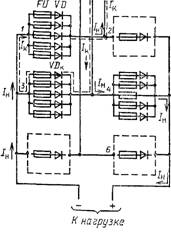
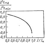
Fig. 16.11. Dependence of pre-arc integrals on the preload current
Fig. 16.10. Protection of semiconductor diodes in a powerful rectifier circuit
The FU fuse is triggered, the damaged diode turns off, and the circuit continues normal operation with some diode overload.