What are the vessels that work under pressure. On each floor of the boiler room there must be at least two outlets located on opposite sides of the room. All safety plates and fuse-links must have a factory stamp with a decree
A vessel working under pressure is called a hermetically sealed container intended for conducting chemical, thermal and other technological processes, as well as for storage and transportation of gaseous, liquid and other substances. The boundary of the vessel is the inlet and outlet connection. The number of pressure vessels includes boilers, cylinders, cisterns, barrels. Vessels working under pressure are made welded or cast in factories authorized by the State Security Inspection. At the plant on the surface of the vessels are given passport data. After manufacturing, all vessels must be tested with a test pressure.
During operation, the most common causes of accidents and vascular explosions are: exceeding the maximum permissible pressure, violation temperature conditions, their loss of mechanical strength.
Vessels working under pressure, because of the possibility of explosion, are equipment of increased danger, therefore, they must be operated in accordance with the "Rules for the device and safe operation vessels working under pressure. " These rules apply to: vessels operating under water pressure with a temperature above 115 ° C or other liquid with a temperature exceeding the boiling point at a pressure of 0.07 MPa (without hydrostatic pressure); vessels operating under the pressure of steam or gas above 0.07 MPa; cylinders intended for transportation and storage of compressed, liquefied and dissolved gases at a pressure of more than 0.07 MPa; cisterns and barrels for transportation and storage of liquefied gases, whose vapor pressure at temperatures up to 50 ° C exceeds 0.07 MPa; cisterns and vessels for the transportation or storage of compressed, liquefied gases, liquids and solids in which a pressure above 0.07 MPa is generated periodically for their emptying; altitude chambers.
These rules do not apply to: vessels and cylinders with a capacity not exceeding 0,025 m 3 (25 l) for which the product of pressure (p) in MPa per capacity (V) in m 3 does not exceed 0.02; vessels operating under vacuum; steam and water heating appliances; tubular furnaces; parts of machines that are not independent vessels, and some others.
Vessels, which are subject to the "Rules for the Arrangement and Safe Operation of Pressure Vessels", are subject to registration and technical examination - inspection and test by trial pressure. Some vessels are registered in the organs of the State Security Inspection. Registrations in these bodies are not subject to: vessels of refrigeration units and refrigerating units as part of technological installations; barrels for the transport of liquefied gases, cylinders with a capacity of up to 100 liters inclusively installed in a stationary manner, and also intended for transportation and (or) storage of compressed, liquefied and dissolved gases; vessels for storing or transporting liquefied gases, liquids and loose bodies that are under pressure periodically when emptied; containers with compressed and liquefied gases, designed to provide fuel to the engines of the vehicles on which they are installed, and some others.
Trade and public catering establishments do not use vessels that are subject to registration in Gosnadzor-obrabotruda agencies. However, in these enterprises there are vessels or devices that are subject to the requirements of the "Rules for the Arrangement and Safe Operation of Vessels Working Under Pressure". Such vessels include apparatuses of stationary refrigeration units, car heaters, cylinders with various gases.
Permission for commissioning a vessel that is not subject to registration in the bodies of the State Security Inspection is issued by the person appointed by the order for the enterprise to supervise the technical condition and operation of the vessels, on the basis of the documentation of the manufacturer after checking by the representative of the service organization and, if necessary, technical examination. Permission to put the vessel into service is recorded in his passport. The following data should be on the surface of the vessel: the registration number, the permitted working pressure, the date (day, month and year) of the next inspection and test.
The vessel or group of vessels included in the installation are included in the work on the basis of a written order of the administration of the enterprise. Vessels, which are subject to the requirements of the above rules, periodically in the process of operation and, if necessary, ahead of time are subject to technical examination. The scope, methods and frequency of technical inspection of vessels (with the exception of cylinders) are specified by the manufacturers, are specified in the passports and instructions for installation and safe operation. Technical inspection of vessels, cisterns, cylinders and barrels can be carried out at special repair and testing points, at manufacturing plants, at filling stations, and also at the owners' enterprises.
At the enterprises the maintenance of vessels in a serviceable condition and safe conditions of their work should be provided. The order on the enterprise or association of the enterprises is appointed from the number of engineering and technical workers the person responsible for the serviceable condition and safe operation of the vessels and the person who oversees their technical condition and operation. To service of vessels working under pressure, persons who have reached the age of 18, who have passed special training (in vocational school, training and course combine), attestation in the qualification commission and instruction on safe maintenance of vessels are allowed. Check of knowledge of the personnel, serving vessels, is held at least once a year.
Instructions on the mode of operation and safe operation of vessels should be posted at workplaces and issued against receipt to service personnel.
In case of violations of operating modes and the appearance of malfunctions, the operation of the vessels must be stopped.
To control the operation and ensure safe operation, the vessels are equipped with instruments for measuring pressure and temperature, safety devices, stop valves and, if necessary, fluid level indicators.
Pressure gauges are installed on pressure receptacles, which are inspected with sealing or stamping at least once a year. At least once every 6 months, the company verifies the readings of working pressure gauges on the control; the results of the audit are recorded in the log. The manometer should have a red line in division, corresponding to the permitted working pressure in the vessel.
Safety valves are spring and lever-cargo operation. Safety valves must comply with the requirements of GOST 12.2.085-82. "SSBT. Vessels working under pressure. Safety valves. Safety requirements". The pressure setting of the safety valves must be equal to or greater than the working pressure in the vessel, but not more than 25%. The working medium exiting the safety valve should be taken to a safe place. Safety valves are checked at least once every 6 months or once a year, depending on the type of vessel on which they are installed. During periodic checks, the safety valve must be sealed after testing and calibration.
Instead of safety valves, safety plates can be used that burst when the pressure in the vessel exceeds the working pressure by no more than 25%.
A vessel operating under pressure less than the pressure of the source supplying it must be equipped with an automatic reducing device to lower the gas pressure. The low pressure chamber of the reducer must have a pressure gauge and a spring safety valve adjusted to the corresponding permissible pressure in the tank into which the gas is allowed to flow. Such gears are available, for example, in car dealers.
Stop valves are installed on pipelines, through which liquids, vapors or gases are drawn to or from the vessel. The installation of a shut-off valve between the vessel and the safety valve is not allowed. Do not install locking devices on pipes that divert gas or steam from safety devices.
Between the vessel with an extremely dangerous or highly hazardous substance, as well as with a fire or explosive atmosphere and a pump (compressor), a check valve is automatically closed, which is automatically closed by pressure from the vessel.
If it is necessary to control the level of the liquid in vessels having an interface between media, level indicators are used. In addition to level indicators, sound, light and other alarms and level-locking can be installed on the vessels.
The operation of steam and hot water boilers is governed by the "Rules for the Arrangement and Safe Operation of Steam and Hot Water Boilers".
Steam boilers with operating pressure up to 0.07 MPa must meet the requirements of GOST 12.2.096-83. "SSBT. Steam boilers with working pressure up to 0,07 MPa. Safety requirements".
§2. Additional requirements to cylinders,
The vessel is a geometrically closed container intended for conducting chemical, thermal and other technological processes, as well as for storage and transportation of gaseous, liquid and other substances. The boundary of the vessel is the inlet and outlet connections for connecting various communications and devices.
Depending on the operating conditions, the vessels can be mobile (for temporary use in different places or during their movement) and stationary (permanently installed in one particular location).
The working pressure in the vessel can be either excessive (relative to the atmospheric) internal, or excessive external, arising during the normal course of the working process.
The most commonly used vessels are the following:
cylinder - a vessel having one or two necks for the installation of valves, flanges or fittings, intended for the transportation, storage and use of compressed, liquefied or dissolved under pressure gases;
a barrel is a vessel of a cylindrical or other shape that can be rolled from one place to another and placed on the ends without additional supports intended for transportation and storage of the substances mentioned above;
cistern - a mobile vessel permanently installed on the railroad car frame, on the chassis of a car (trailer) or other means of transportation intended for the transport and storage of substances specified above;
tank - stationary vessel, intended for storage of substances, specified above;
The design of the vessel should ensure the reliability and safety of operation during the estimated service life and provide for the possibility of technical inspection, cleaning, washing, complete emptying, purging with gas or steam, repair, operational control of the state of the metal and compounds. The vessel must have the necessary number of hatches and inspection hatches for inspection, cleaning, repair, installation and dismantling of demountable internal devices.
The vessel must be made in a seamless or welded manner. Holes in the walls of the vessel must be outside welded joints.
Materials used for the manufacture of vessels should ensure their reliable operation during the estimated service life, taking into account the specified operating conditions (by pressure, temperature, composition, etc.).
As a material for pressure vessels, steel (carbon and alloyed), non-ferrous metals and their alloys are used. Non-metallic materials can be used only with the permission of the bodies of the Federal Service for Technological, Ecological and Nuclear Supervision of the Russian Federation (Rostekhnadzor, RTN) on the basis of the conclusion of a specialized organization.
All welded joints of pressure vessels should be subjected to non-destructive testing for defects.
The main danger in the operation of vessels is the possibility of their destruction during sudden adiabatic expansion of gases and vapors (physical explosion). In the case of a physical explosion, the potential energy of the compressed medium during a short time interval is realized in the kinetic energy of the fragments of the destroyed vessel and the shock wave.
Especially dangerous are explosions of vessels containing flammable substances, as this causes a chemical explosion, which is the cause of the fire.
When explosions of vessels develop large capacity, which is the cause of severe destruction. So, for example, when a vessel V = 1 is broken with a compressed air up to P = 1.2 MPa with a duration of a physical explosion of 0.1 s, a power equal to 28 MW develops.
The most common causes of vascular accidents involving pressure are:
- non-compliance of the design with the maximum allowable pressure and temperature;
- excess pressure beyond the limit for a given vessel;
- loss of mechanical strength due to internal defects, corrosion, local overheating, etc .;
- non-compliance with the established operating mode;
- low qualification staff;
- lack of technical supervision.
Since most often in the fuel and energy complex production facilities are used cylinders for transportation, storage and use of compressed, liquefied and dissolved gases, we will consider in more detail the hazards arising from their operation.
Explosions of cylinders are possible if the hull is damaged in the event of a fall or impact on the cylinder, especially at a temperature< –30 оС, т. к. при этом повышается хрупкость стали. Взрыв может произойти и при повышении температуры из-за роста давления среды в баллоне.
The cause of the explosion can also be the overflow of the cylinder with liquefied gases due to a sudden increase in pressure with increasing temperature, which is explained as follows. When the temperature of the cylinder completely filled with liquefied gas increases, the value of the increased pressure is calculated by formula
p = Δt · α / β (15)
where: Δt - range of temperature rise of the contents of the cylinder, deg .;
α is the coefficient of volumetric thermal expansion of the gas contained in the cylinder;
β is the coefficient of volumetric thermal compression of the liquefied gas contained in the cylinder;
For most gases used in industry, the value of α is greater than β by an order of magnitude, which, with an increase of Δt by 10 degrees, gives a pressure increase of 100 atm.
Explosions of cylinders containing compressed oxygen are possible when oil and other fatty substances enter the interior cavity of the valve or bottle due to the use, for example, of non-fattening sealing gaskets. In an oxygen environment, oils and fats are oxidized to peroxides that are decomposed by explosive methods, in addition, oils and fats in the oxygen stream are capable of self-igniting, which also results in the explosion of the cylinders.
Cylinders with hydrogen are dangerous if the hydrogen contained in them is contaminated with oxygen in an amount of\u003e 1% by volume, since an explosive mixture is formed that ignites explosively in the presence of an appropriate pulse.
Cylinders with acetylene are dangerous because of the possibility of this substance decomposing with an explosion in the absence of oxygen at a pressure\u003e 0.2 MPa. Because of this circumstance cylinders with acetylene are filled with activated carbon, which is impregnated with acetone, which allows to increase the gas pressure in the tank to 1.6 MPa.
Accidents of cylinders are also due to the lack of information about the substance contained in them when it is fully consumed, as well as the lack of an identification coloring of the surface of the balloon and the corresponding inscriptions, as a result of which an air or a combustible substance can be poured into the cylinder, which leads to the formation of an explosive mixture and explosion in the presence of a corresponding ignition pulse.
Since bottles may contain toxic substances, when they are depressurized, there is also a risk of poisoning of personnel with toxic substances.
Other abstracts:
- Subject, content and tasks of industrial safety
- Categorization and classification of production facilities as a measure of hazard assessment
- The main causes of industrial injuries and accidents
- Indicators of industrial injuries and accidents
- Development, approval, approval and composition of design documentation for production facilities
- Requirements for the reliability of production equipment
- Safety requirements for the main production equipment
- Requirements for protective equipment included in the design of production equipment and signaling devices
- Structural materials of production equipment
- Reduction of noise and vibration levels in gears and gearboxes
- Reduction of noise and vibration caused by unbalanced masses of rotating parts
- Reduction of vibration of production equipment through vibration absorption and vibration isolation
- Hazards arising from the operation of pressure vessels
- Basic measures for the safe operation of pressure vessels
- Installation, registration, technical inspection and authorization for the operation of pressure vessels
Safety in the operation of pressure systems
1. General requirements for pressure vessels
The enterprises widely use systems with pressure vessels: gas and hot water boilers, compressor units, autoclaves, steam and gas pipelines, gas cylinders, tanks and drums for transportation and storage.
Vessels working under pressure represent a potential danger because due to violation of the operating regime and defects, explosions can occur with the destruction of buildings, structures, equipment and loss of life due to the release of huge energy when the vessel is destroyed.
During the explosion, expansion takes place, the compressed gas (adiabatic process) in it, practically without loss of energy to the environment.
The power of the explosion is determined by the formula (kW):
,
where A is the gas expansion work, J;
102 - conversion coefficient of the dimension kg * m / s in kW;
t is the duration of the explosion, s.
Pressure vessels are hermetically sealed containers that are designed for chemical and thermal processes, as well as for storing and transporting compressed, liquefied gases and liquids.
The basic requirements for the device, installation, repair and operation of pressure vessels are set out in the DNDOP 0.00-1.07-94 "Rules for the Arrangement and Safe Operation of Vessels Working Under Pressure." These rules apply to:
vessels that operate under the pressure of water with a temperature above 115 ° C or with another liquid with a temperature that exceeds the boiling point at a pressure of 0.07 MPa (0.7 kgf / cm2), without hydrostatic pressure;
vessels that operate under steam or gas pressure above 0.07 MPa;
cylinders intended for transportation and storage of liquefied and compressed gases at a pressure above 0.07 MPa;
cisterns and barrels for transportation and storage of liquefied gases, the pressure of gases in which, when heated to 50 ° C, exceeds the pressure of 0.07 MPa;
cisterns and vessels for transportation and storage of liquefied and compressed gases, liquids and solids, in which the pressure is above 0.07 MPa, opened periodically to empty them;
altitude chambers.
The rules for the construction and safe operation of pressure vessels do not apply to:
steam and water heating appliances;
vessels and cylinders with a capacity of no more than 25 liters, in which the product of capacity in liters per working pressure (MPa) is not more than 20 liters MPa;
vessels made of non-metallic materials;
vessels operating under water pressure at a temperature not exceeding 115 ° C and pressure vessels of other liquids at a temperature not exceeding the boiling point and a pressure of 0.07 MPa.
Depending on the temperature and pressure of operation, the vessels are divided into 4 groups (Table 3.3.1).
Vessels before commissioning must be registered in the expert technical centers (ETC) of the State Supervision. Registration in the ETC is subject to:
pressure vessels, non-corrosive and non-explosive environments with a wall temperature of more than 200 ° C and subject to inequality (2,3 and 4 groups)
where P - working pressure, MPa (kgf / cm2);
V is the volume, m3 (l).
Vessels with caustic and explosive environments with a temperature of more than 200 oC, subject to inequality (1 group), cylinders with a capacity of more than 200 liters for transportation and storage of compressed, liquefied and dissolved gases.
Not subject to registration in the ETC:
vessels of the 1st group that operate at a temperature of no more than 200 oC, in which the product of pressure in MPa (kgf / cm2) per volume in m3 (l) does not exceed 0.05 (500);
vessels 2, 3 and 4 groups operating at the above temperature, for which the product of pressure in MPa (kgf / cm2) per volume in m3 (l) does not exceed 1 (10,000);
barrels for transportation of liquefied gases, cylinders with a capacity of up to 100 liters inclusive, which are installed permanently, and also intended for transportation and storage of liquefied, compressed and dissolved gases;
vessels for the preservation or transportation of liquefied gases, liquid and bulk bodies that are under pressure periodically when emptied;
containers with compressed and liquefied gases, which are intended to provide fuel to engines of vehicles for which they are installed; some other vessels.
Table1. Vessel groups depending on the design pressure.
|
Group of the vessel |
Design pressure, MPa (kgf / cm2) |
Temperature, ° C |
Nature of the working environment |
|
|
More than 0,07 (0,7) |
Regardless of |
Explosion - or fire hazard, or 1,2 th class of safety in GOST12.1 007 |
||
|
More than 2.5 (25) More than 4 (40) More than 5 (50) |
Below -70 above 400 Below -70 above 200 Below -70 above 200 Regardless of |
Any, except for the vessels indicated for the first group |
||
|
More than 1.6 (16) to 2.5 (25) More than 2.5 (25) to 4 (40) More than 4 (40) to 5 (50) |
-70 to -20 200 to 400 -70 to 400 -70 to 200 -40 to 200 |
Any, except for those indicated for the first and second groups of vessels |
||
|
-20 to 200 |
Vessel registration is carried out at the written request of the owner of the vessel with the presentation of: a passport for the vessel, certificates of the quality of the assembly, schemes for including the vessel (indicating the operating parameters), safety valve passports indicating the estimated throughput.
Permission for commissioning of vessels subject to registration is issued by the inspector of supervision after their registration and technical examination.
Permission to launch vessels that are not subject to registration in supervisory bodies is issued by the person appointed by the order for the company to supervise them, on the basis of the results of the technical survey. These permits (with the indication of the period of the next technical survey) are recorded in the passport and the "Book of registration and examination of the vessel."
Technical inspection of vessels subject to registration in the ETC is carried out by representatives of the State Supervision of Labor Protection in the presence of representatives of the technical service of the enterprise. Vessels that are not subject to registration in the bodies of the State Supervision of Labor Protection by the person responsible for their technical and safe condition at the enterprise. The technical survey includes external and internal inspection and pressure testing, according to the vessel certificate.
When the vessel is moved to a new location or transferred to another owner, and the scheme of its operation is changed, the vessel must be re-registered.
To serve pressure vessels, persons who are not younger than 18 years old, have passed a medical examination, trained according to the approved program, certified with the issuance of a certificate for the right to perform works may be admitted.
Certification of personnel who work with pressure receptacles of hazardous substances of 1, 2, 3 and 4 hazard classes according to GOST 12.1 007 is carried out by a commission with mandatory participation of a representative of the State Supervision of labor protection (in other cases, the participation of a representative of the State Supervision of labor protection in the commission is not necessary). Checking the knowledge of personnel serving vessels operating under pressure is conducted at least once a year.
An extraordinary examination of the knowledge of the personnel is carried out in the following cases:
with a break in work for more than 12 months;
at the request of the representative of the State Supervision of Labor Protection in case of violations in the work of personnel or technical condition of the vessel;
when changing the place of work;
when changing the type or group of vessels operating under pressure;
when the circuit and operating mode of the pressure vessel change.
Considering the high potential risk of pressure vessels, instructions must be posted at the workplace safe work, the order of admission and inclusion. It is forbidden to be in the workplace with pressure vessels to unauthorized persons.
2. Safety during operation of steam and water-heating boilers
"Rules for the installation and safe operation of steam and water boilers" establish requirements for the installation, adaptation, installation, repair and operation of steam boilers, autonomous superheaters and economizers with a working pressure of more than 0.07 MPa (0.7 kgf / cm2), water boilers and autonomous economizers with a water temperature above 115 ° C.
Explosions of steam boilers are the instantaneous release of the energy of superheated water and the reduction of pressure to atmospheric. This is an adiabatic explosion. At atmospheric pressure, water boils at 100 ° C in an open vessel. In closed - boiling starts at 100C, steam presses on the surface of the water - and boiling stops. To boil continued, it is necessary to heat the water to a temperature corresponding to the vapor pressure. For example, at P = 0.6 MPa (6 kts / cm2) - T = 169C, at P = 0.8Mpa - 171C, at P = 1.2Mpa - 189C, at P = 1.96MPa - 211C. If the water is stopped at 190 ° C and the steam is used normally, the water will boil until its temperature is below 100 ° C, and the more steam is taken, the more boiling and vaporizing will be due to the excess energy contained in the water. This excess of heat energy (from Rmakh to Rathm) is completely spent on steam generation. Overheated water up to 190С entirely turns into steam: from 1 m3 of water, 1700 m3 of steam is formed. Consequently, the danger is not hidden in the steam that is in the boiler, but in the water heated above 100C which has a huge reserve of energy and is ready to evaporate at any moment with a sharp drop in energy. Therefore, the more water in the boiler per unit heating surface, the more accumulated heat in it and the more explosive the boiler. Reliably designed and manufactured according to specifications with proper maintenance and control, the pressure vessel will never explode. The destructive energy of superheated water is comparable to gunpowder - 60 kg of superheated water to 160 ° C, P = 0.5 Mpa, according to the explosion energy = 1 kg of gunpowder.
The cause of the explosion may be: excess of design pressure due to faulty safety valves; a lowering of the water level, when the heated walls cease to be cooled by water; deterioration of the plant from long-term operation; violation of technical requirements operation; design deficiencies and material mismatch with design parameters.
Steam boilers with a furnace, waste heat boilers, boiler boilers are subject to control and registration of the State Supervision Authority, if the working pressure in them exceeds 0.07 MPa, water heaters with a furnace are also subject to control if the temperature in them is more than 115 ° C. Installations with a pressure less than 0,7 MPa (0,7 kgs / cm2) are subordinated to the technical administration of construction departments and enterprises.
Under the rules of the State Supervision Authority, each steam boiler is equipped with: safety valves with pressure gauges (working and control); water-indicating devices, thermometers; shut-off valve and check valve on the heating line of the boiler supply with water; drain valve with a gate (protective equipment).
The number of safety valves, their dimensions and throughput should be selected according to the following calculation: a boiler with a steam production capacity of more than 100 kg / h must be equipped with at least two safety valves, on boilers with a capacity of less than 100 kg / h, one safety valve is installed.
Fig. 1. Measuring and safety devices
The total throughput of safety valves installed on the boiler must be at least the hourly capacity of the boiler.
Safety valves should be placed in places accessible for inspection. The working medium exiting the safety valve must be diverted to a safe place.
Installation on the drainage and drainage pipes of the locking bodies is not allowed.
The amount of steam that can pass a safety valve at a boiler pressure of 0.07 MPa to 2 MPa is as follows:
for saturated steam:
for overheated:
If in boilers the vapor pressure is more than 12 MPa, then the amount of steam
where D n. etc., Dn. p., D - the throughput of the valve, kg / h: b - the coefficient of steam (liquid) flow by the valve, is determined experimentally by the design organization (manufacturer) for each valve design and recorded in the passport; P1 - maximum overpressure in front of the safety valve, MPa Vn. etc., Vn. v. V - specific volume of steam in front of the safety valve, m3 / kg; F is the cross-sectional area of the valve, equal to the smallest sectional area in the flow section, mm. Distinguish spring and lever safety valves (Fig. 1-2).
Fig. 2. Lever safety valve
1 - counter from; 2 - lever arm; 3 - valve body
The number and diameter of the passage of safety valves installed on water-heating boilers are determined by the formula
where n is the number of safety valves;
d - diameter of valve seat in light, cm;
h - valve lift height, cm;
Q - maximum heat output of the boiler, J;
k - empirical coefficient: for low-lift valves k = 135 (h / d? 1/20), full-lift valves - k = 70 (h / d? 1/4);
P is the absolute maximum permissible pressure in the boiler when the valve is fully open, MPa;
i - enthalpy of saturated steam at the maximum permissible pressure in the boiler, J; t V.X. - temperature of water entering the boiler, ° С.
The supplier must send a passport and operating instructions to the safety valve.
If the safety valve can not be reliably operated by the nature of the production or due to the harmful nature of the medium in the vessel, then the vessel must be equipped with a safety plate that ruptures when the pressure in the vessel is not more than 25% of the working pressure.
The safety plate (diaphragm) can be installed in front of the safety valve, provided that there is between them a device that allows monitoring the serviceability of the plate.
In the wall of the boiler from the furnace side, safety inserts (plugs) made of a low-melting (lead-tin) alloy are installed.
With a lack of water, the heating of the plug leads to its melt.
All safety plates and fuse-links must have a factory stamp indicating the pressure that breaks the plate, or the reflow temperature.
Fig. 3. Relief Valve Diagram
Each vessel should be equipped with a pressure gauge, which is installed on the container body, on the pipeline to the stop valves or on the control panel. The manometer reading should be clearly visible to the service personnel. In this case, the scale should be either in the vertical plane, or inclined forward to 30 ° (Figure 4). Installation of pressure gauges at an altitude of more than 5 m from the level of the service area is prohibited. The nominal diameter of the pressure gauges installed at an altitude of 2 to 5 m from the observation site shall be not less than 160 mm. A three-way valve must be installed between the manometer and the vessel.
On the vessels, gauges with an accuracy class of at least 2.5 and with such a scale are installed so that the limit of measuring the working pressure is in the second third of the scale. At the division corresponding to the working pressure in the vessel, a red line is drawn or a metal plate, painted in red, is attached.
The pressure gauge is forbidden to use if there is no seal or stigma, or the needle of the manometer does not return to the zero mark when it is turned off, or the glass is broken. Checking gauges and sealing them must be done at least once a year. In addition, at least once every six months the enterprise conducts an additional check of the manometers with a control manometer or a verified worker with a record of the results in the audit log.
For boilers with a steam capacity of less than 0.7 t / h, one of the water meters can be replaced by two plug cocks or valves. The lower tap, or the valve, is set at the minimum level, and the upper one - at the level of the maximum permissible water level in the boiler.
At each newly manufactured steam boiler, for constant monitoring of the water level, at least two direct-acting water indicators must be installed (Figure 5).
Fig. 4. Manometers:
a, b - working manometers; and control; 1,2 - springs;
3 - arrow; 4 - the gear drive; 5 - the hinge; 6 - the shoulder;
7 - nipple; 8 - the rack;
9 - scale; 10 - housing;
11 - a cogwheel;
12 - manometers; 13 - the crane;
14-flannel;
16 - a tube of a siphon.
Fig. 5. Water level indicator in the boiler: water glass
Fig. 6. The scheme of installation of instrumentation on a steam boiler: VUV - the highest water level; НУВ - the lowest level of water.
The internal diameter of the test tap, or valve, must be at least 8 mm. The water indicator device is designed so that it is possible to replace the glass or housing when operating the boiler. A fixed metal pointer with the inscription "Minimal level" shall be installed on the water meters against the permissible minimum water level in the boiler. This level should be no less than 25 mm above the lower visible edge of the glass. If the distance from the site to be monitored to the directional water meter is more than 6 m, two reliably operating remote level indicators are installed.
The shut-off valves must be installed on pipelines supplying steam and gas or liquid from the vessel. When serial connection several vessels installation of a stop valve between them is not necessary. Do not install a shut-off valve between the vessel and the safety valve. The installation of a switching tap or a three-way switching valve between the valve and stationary vessels is allowed if both safety valves are connected at any position of the plug, or valve spindle. On the flywheels of the stop valves, the direction should be indicated when opening and closing them. In the presence of an explosive atmosphere or strong poisons on the supply line from the pump or compressor, a non-return valve is installed, automatically closed by the pressure of the vessel. The non-return valve must be installed between the pump (compressor) and the shut-off valve. The valves must be clearly marked (manufacturer, conditional pass, conditional pressure, flow direction of the medium).
Boiler rooms should not be adjacent to residential and public buildings, as well as creep inside these buildings (built-in premises). Adjacent boiler houses to production premises are allowed provided they are separated by a fire wall with a fire resistance limit of at least 4 hours. The doors must open towards the boiler rooms. The installation of any rooms directly above the boilers is not allowed.
Inside the production premises, as well as above and below them, the installation is allowed:
direct-flow boilers with a steam capacity of no more than 4 t / h;
boilers satisfying the condition:
(for each boiler),
where t is the saturated vapor temperature at the working pressure, ° C;
V - volume of the boiler, m3;
water boilers with a heat output of not more than 10,460 J / h.
The places of installations of boilers inside the production premises, above or below them, should be separated from the rest of the premises by fireproof partitions throughout the height of the boilers, but not less than 2 m with the installation of doors to the boilers.
In production premises adjacent to living quarters, separated from them by boiler walls, installation of steam boilers is permitted, for which
,
where t is the temperature of the liquid at the working pressure, ° C;
V - volume of the boiler, m3.
On each floor of the boiler room there must be at least two outlets located on opposite sides of the room.
As a precautionary measure, when boilers with chamber combustion of all types of fuel and with mechanical furnaces solid fuel a safety automat must be installed, which must interrupt the fuel supply when it ceases or falls below the working gas operating limit, when the power supply is cut off and the blowers are switched off, when the smoke exhauster is switched off or the traction is stopped, and the automation is malfunctioning.
Automation should work when the limit values are reached: the water level in the steam boiler; steam pressure in the steam boiler; water temperature at the outlet of the water-heating boiler; water pressure at the outlet of the water-heating boiler; discharge in the furnace for boilers with balanced traction.
One of the security measures for working personnel is the installation of tape glazing along the entire front of the boiler houses. In this case, the thickness of the glazing should not be more than 3 mm.
3. Safety when operating pressure vessels
Vessels working under pressure are equipped in the same way as boilers, safety valves, pressure gauges, thermometers, valves, etc. The requirements for them are basically the same, but there are differences.
According to calculations, the number of safety valves, their dimensions and throughput are set taking into account that the vessel can not generate a pressure exceeding the working pressure by more than 0.05 MPa for vessels with a pressure up to 0.29 MPa inclusive; by 15% for vessels with a pressure of 0.29 MPa to 5.8 MPa; by 10% - for vessels with a pressure in excess of 5.8 MPa.
The throughput, kg / h, of the safety valve is determined by the formula
where P1 and P2 are the overpressure respectively before and behind the safety valve, MPa; j is the density of the medium for the parameter P1, N / m3; B is a coefficient, for liquids, equal to 1. The coefficient B for gases is determined from Table 15 of the Rules for the Arrangement and Safe Operation of Pressure Vessels.
Vessel service should be entrusted to persons who have reached the age of 18 years and have undergone industrial training, attestation in the qualification commission and instruction on safe maintenance of vessels. Persons who passed the test must be issued with certificates. At the enterprise the chief engineer develops and approves the instruction on a mode of work and safe service of vessels. Instructions are given to the attendants and posted in the workplace; at least once a year by a commission appointed by an order for an enterprise, a knowledge check is carried out, which is documented by the protocol.
In no case is it allowed to repair the vessels during operation. The vessel must be turned off when:
excess pressure in the vessel is higher than allowed;
failure of safety valves, pressure gauge, liquid level indicator, safety interlocked devices for instrumentation and automation;
detection of cracks, bumps, thinning of walls, fogging, leaks in riveted and bolted joints, rupture of gaskets;
the occurrence of a fire directly threatening the vessel under pressure;
lowering of the liquid level below the permissible level in vessels with fire heating;
malfunction or incomplete number of fasteners of covers and hatches.
Vascular examination is performed during their work at least once a year. All elements of boilers, pipelines, superheaters and auxiliary equipment with a wall temperature of the outer surface above 43 ° C in accessible locations should be covered with thermal insulation.
Hydraulic tests are subject to all vessels after their manufacture. At a wall temperature of up to 200 ° C, all vessels, except for casting with working pressure P1 = 0.49 MPa, are tested by the manufacturer for a test pressure of l, 5PN, but not less than 0.2 MPa; with operating pressure above 0.49 MPa are tested for a test pressure of l, 25PН, but not less than 0.29 MPa. Cast vessels, irrespective of the operating pressure P1, are tested for 1.5 RP pressure, but not less than 0.29 MPa. The holding time under test pressure should be for vessels with wall thickness: up to 50 mm - 10 min; 50-100 mm - 20 minutes; over 100 mm - 30 minutes; cast - 60 min.
In hydraulic tests, water is applied at a temperature equal to the ambient temperature. The vessel is considered to have withstood a hydraulic test if no signs of rupture, leakage and sweating in welded joints and on the base metal, visible residual deformations are found. Hydraulic tests are conducted at least once every 8 years.
The main reasons for the explosions of cylinders are:
blows or drops of cylinders (especially dangerous when the walls are heated or at minus temperatures);
overflow of gas cylinders;
excessive heating or cooling of cylinders;
filling of cylinders with another gas (use of cylinders for other purposes);
excessively rapid filling of cylinders with liquefied gas (which leads to overheating of the cylinder bulbs up to 400 ° C);
ingress of oils or explosive dust;
formation of rust, scales, sparking;
To avoid explosion, carbon or alloyed steel is used in the production of cylinders; at pressures up to 3 MPa, the use of welded cylinders is allowed, at higher - seamless.
To avoid an explosion, if special (fast) filling or gas consumption is used, special valves with pressure reducing valves and pressure gauges (one working, the other control) are installed.
As a precaution, at least 10% of the filled volume is left in the filling of cylinders (90% is filled), to keep other gases, dust or oils from getting into the balloon, the residual pressure of at least 0.05 MPa (for acetylene 0, 05-0.1MPa). Cylinders are subjected to hydraulic tests on special stands (a certain number of cylinders are taken from a batch) with a pressure of 1.5 more working.
Hydraulic testing in factories also involves cylinders in accordance with regulatory documents. After that, all cylinders (except cylinders used for acetylene) are immersed in baths with water and subjected to a pneumatic test with a pressure equal to the working pressure.
Cylinders in service must be periodically inspected at least 5 years from now. Cylinders for liquefying compressed gases used for fuel and causing metal corrosion (chlorine, methyl chloride, hydrogen sulphide, hydrogen chloride) are to be tested after 2 years.
Fig. 7. Scheme of the stand for hydraulic testing of cylinders:
1 - a cylinder; 2 - mobile ream for changing the installation height of the fitting; 3 - fitting; 4 - manometer; 5 - steel protective cabinet; 6 - the lever; 7 - the hydraulic drive; 8 - water tank.
The permit for survey is issued to enterprises - fillers, filling stations and test points by the State Supervision of Labor Protection.
Examination of cylinders, except for cylinders for acetylene, includes: inspection of the inner and outer surfaces of cylinders; verification of mass and capacity; hydraulic testing.
If the inspection revealed cracks, dents, shells and risks more than 10% of the normal wall thickness, tears, thread wear of the neck, the cylinders are rejected. For internal inspection of cylinders, a voltage of no more than 12 V is applied in an explosive design. The balloon, which has an oblique or weak shoe attachment, is not allowed to be further inspected.
To avoid misuse of cylinders, they are painted in the appropriate color and labeled (Table 3.3.2), and the side valves of the valves must have different threads (for oxygen and inert gases - right, for combustible - left).
Seamless standard cylinders with a capacity of 12 to 55 liters with a mass loss of 7.5 to 10% or an increase in capacity by 1.5-2% are transferred to a pressure below the set value of 15%. With a mass loss of 10-15% and an increase in capacity by 2-2.5%, the cylinders are transferred to a pressure below the set value of 50%. With a mass loss of 15-20% and an increase in capacity in the range of 2.5-3%, the cylinders are allowed to work at a pressure of not more than 0.58 MPa. With a mass loss of more than 20% and an increase in the capacity of more than 3%, the cylinders are rejected.
Cylinders for acetylene, made of a porous mass, are tested under nitrogen at a pressure of 3.4 MPa (nitrogen purity must be at least 97%).
In this case, the cylinders must be immersed in water to a depth of at least 1 m. For long-term storage of gas-filled cylinders, at least 5 pcs. Of samples are randomly sampled. from a batch of 100 cylinders; 10 - out of 500; 20 - more than 500 cylinders. If the results are satisfactory, the shelf life is established no more than 2 years.
Table2 . Marking of cylinders
|
Cylinder Color |
Band Color |
||||
|
Brown |
|||||
|
Argon is pure |
Argon is pure |
||||
|
Acetylene |
Acetylene |
||||
|
Neftegaz |
Neftegaz |
||||
|
Hydrogen sulfide |
Hydrogen sulfide |
||||
|
Dark green |
|||||
|
Compressed air |
|||||
|
Brown |
|||||
|
Oxygen "medical" |
Oxygen "medical" |
||||
|
Sulphurous anhydrite |
Sulphurous anhydrite |
Cylinders with gas installed in rooms should be located from the radiators at a distance of not less than 1 m, and from heat sources with open fire - not less than 5 m. In the welding workshop it is allowed to have one spare cylinder with oxygen and acetylene.
Cylinders with all toxic gases can be stored both in special rooms and on open air subject to protection from precipitation and sunlight.
Warehouses for storage of cylinders should be one-story, with overlappings of easy type, without attics. The height of the storage space for cylinders must be at least 3,25 m. Walls, partitions and floors of warehouses must be made of fireproof materials of at least 2 degrees of fire resistance; windows and doors - open outwards; window and door glass should be matte or painted with white paint; warehouses - must have an artificial or natural ventilation. The floors of warehouses must be made even with a non-slip surface. Warehouses can be made under canopies with a fence made of mesh. Warehouse storage of cylinders with oxygen and combustible gases in one room is prohibited. Warehouses are divided into compartments for storage of not more than 500 cylinders (40 liters each) with flammable or poisonous gases and not more than 1000 cylinders with non-toxic and non-flammable gases.
Cylinders mark - knock out on the upper spherical part of the metal case data: trademark, stamp of the manufacturer OTK, cylinder number, actual empty cylinder weight (kg), cylinder capacity (L), working and trial hydraulic pressure (MPa), date (month and year) ) of manufacture and the date of the next survey.
When stacking cylinders in stacks, the height of the latter should not exceed 1.5 m, the valves should be facing in one direction.
Transportation and storage of standard cylinders with a capacity of more than 12 liters is made with capped caps. Transport of filled cylinders is possible only on spring vehicles.
As a gasket used wooden bars with cut out for the cylinder nests. Cylinders can be transported in vertical position in special containers. On the cylinders should be rubber rings with a thickness of at least 26mm (two rings for each cylinder) or other pads that protect against shocks. When unloading, they should be removed with the shoe down.
4. Safety during operation of autoclaves
Autoclaves are used in the construction industry for the heat treatment of silicate products, foam and aerated concrete, silicate bricks, impregnation of wood, etc.
Accidents with autoclaves can occur due to exceeding the vapor pressure above the allowable, opening the lids when there is a pressure of more than 0.01MPa (0.1kgs / cm2) in the autoclave, steam inlet with incomplete closure of the lids, and maintenance personnel inside the autoclave.
Autoclaves for safe work are supplied, as well as pressure vessels, safety and shut-off valves, instrumentation.
Accidentless work of autoclaves is achieved by the quality of production, operating mode, timely technical inspection and preventive maintenance in a timely manner.
In order to avoid accidents, autoclaves are equipped with a locking system that excludes the entry of steam into the autoclave with not completely closed lids, and also the opening of the lids, in the presence of pressure in the autoclaves.
In Fig. 8 shows the scheme of automatic blocking of the autoclave lid in the presence of pressure in it.
From the autoclave (Figure 8) through a condensation vessel 8 steam enters the pressure switch 7 and, by bending the rubber membrane 5 , drives the rod 6 . The latter rests on the switch 4 and breaks electrical circuit electromagnetic lock 9 . In this case, the electromagnetic lock releases the core 10 , which under the action of a spring 11 closes the latch 12 . The latter does not allow to rotate the handle 13 worm winch 14 and thus prevents the cover from rotating 15 autoclave in the shutter.
If the vapor pressure in the autoclave is removed, then the electrical network of the lock 9 is closed by a switch 4 , the core 10 retracts into the electromagnet and opens the clamp 12 . This allows the handle 13 to rotate to open the autoclave lid.
Fig. 8. Automatic blocking of the autoclave cover.
The scheme for automatically blocking the steam supply to the autoclave (Figure 9) excludes the possibility of the steam entering the autoclave if the autoclave lid is not closed. The end switch 2 is placed on the autoclave 1, which operates if the cover 3 is tightly closed and the rod 4, having overcome the force of the spring 5, acts on this switch. When the circuit is closed, the electromagnet 6 compresses the spring 7 and lifts the stopper 8 and releases the ratchet wheel 9. After this, the handwheel 10 connected to the ratchet wheel can be rotated to allow steam to enter the autoclave through the valve 11.
During the operation of autoclaves, a system is used, in which the worker-proparator during the steaming of the products locks a token with the number of the autoclave and the number of its cover in its cabinet. Having finished the steaming and removing the pressure in the autoclave, the cheater transfers the counter to the loader-unloader, who has the right to open and close the autoclave lid. After completing the work, the person who is discussing the autoclave closes the lid, and returns the mismatch to the picker. The badge system allows to avoid violation of the rules of safe maintenance of the autoclave and to prevent accidents.
Fig. 9. Diagram of automatic inlet of steam into an autoclave
5. Safety of operation of compressor units
When operating stationary, reciprocating and dismountable compressors, the requirements of the "Rules for the Arrangement and Safe Operation of Stationary Compressor Units, Air Pipelines and Gas Pipelines" shall be complied with.
The basis for the operation of compressor plants, where the working medium is compressed air, is a polytropic process. When compressing gases in the compressor, the temperature rises while PVm = const.
The temperature increases according to the expression:
,
where T1 and T2 - the absolute temperature of the gas, respectively before compression and after, K;
P1 and P2 - gas pressure respectively before and after compression, Pa;
m is the index of polytropy.
From Table 3.3.3, it is seen that with an increase in pressure of more than 0.5 MPa in the compressor plant, the temperature rises to 230? C, which creates a fire and explosion hazard when combustible dust, fibers or lubricants enter the compressor.
Table 3 . Temperature changes in the compressor, depending on the pressure.
Explosions during the operation of compressors can occur due to:
excess pressure compression normative;
excess of the heating temperature and the formation of explosive mixtures of the decomposition products of lubricant oils with air oxygen;
violation of the requirements for the operation of preventive maintenance;
violation of the cleaning schedule;
suction of explosive gases, dust, fibers, oils, etc. into the compressor.
Thus, if low-temperature oils get into the compressor at an air concentration of 6-11%, the explosion is possible at a pressure of 0.05 MPa and at a temperature of 200 ° C.
To achieve the safe operation of compressor plants, they must be equipped (Figure 10):
pressure gauges (one working, second control), thermometers and thermocouples at each stage of the compressor;
pressure gauges and thermometers for monitoring the pressure and temperature of lubrication oils with automatic lubrication;
safety valves on each compressor stage;
alarm system and automatic shut-off of the compressor when the temperature and pressure exceed the permissible values, shut-off valves, the system remote control and control of the compressor plant.
As preventive measures it is necessary:
timely removal of deposits and deposits of the cylinders and working chambers of the compressor (deposits and deposits are removed every 6 months). The carbon deposits and deposits are removed by steaming a 2-3% solution of the sulfate or methyl solution and then cleaning;
the use of special heat-resistant, cleaned lubricants with an ignition temperature of 75% above the temperature of the working gases of the compressor (the oils must be oxidatively resistant);
application of a reliable multi-stage air and water cooling system; Air cooling is generally used in low-pressure low-pressure compressors, as well as in refrigeration compressor compressors. In high-pressure compressors, water cooling is used. In installations, automation systems must be installed to shut off the compressor when the critical cooling temperature is exceeded (the temperature of the cooling water leaving the compressor must not exceed 40 ° C);
application of multi-stage cleaning of air intake (ceramic filters, felt, etc.) The intake air intake of the air compressor must be made outside the building of the compressor station at a height of not less than 3 m from the ground level;
to avoid sparking due to the formation of static electricity discharges, the compressors are grounded. Filters are subject to periodic, timely, clean-up or replacement;
to prevent hydraulic shocks, condensate is drained from the compressor cooler and humidity control of the incoming air to the compressor (humidity not more than 60%) is provided.
in compressor units equipped with refrigerators, there must be a moisture separator on the pipeline between the condenser and the air collector. Air collectors need to be purged every day through a safety valve and drain the accumulated oil and moisture. For periodic inspections and repair of air collectors, it is necessary to provide for the possibility of their disconnection from the network (oil and water during purging should be diverted to special receivers). The air collector must be installed on the foundation outside the compressor building and must be fenced.
to reduce the fire hazard in oxygen compressors for lubrication use distilled water with the addition of glycerin or apply self-lubricating bushes and rings on graphite (oil lubrication is forbidden);
protection of oxygen compressors from oil ingress is achieved by installing between the slider and the cylinders a lubricant with oil-ring rings;
safety in the operation of compressors for compressing acetylene is achieved by the slow stroke of the piston (no more than 0.7-0.9 m / s) and the cooling system (the temperature on the discharge line should not be more than 50? C);
To lubricate the cylinders of compressors for the compression of chlorine, sulfuric acid (monohydrate) is used;
Compressor plants with a capacity of more than 20 m3 / min should be located in separate buildings. It is not allowed to place equipment and apparatus not connected to the operation of the compressor in the premises of compressor units. The overall dimensions of the room must satisfy the conditions for safe maintenance and repair of the compressor plant equipment. Passages in the engine room must be at least 1.5 m., And the distance between the equipment and the walls of the building is not less than 1 m. The floors of the compressor room must be smooth and non-slip surface, oil resistant, and made of a non-combustible, wear-resistant material. The doors and windows of the compressor rooms must open outwards.
Compressor room should be equipped with exhaust ventilation, telephone. Equipment in the machine hall should be installed taking into account the reduction of vibration to structural elements, as well as compensating devices. All moving and rotating parts of compressors, electric motors and other mechanisms must be protected with the installation of safety signs.
Ammonia refrigeration facilities are located in separate rooms with fire safety standards. Gas-like ammonia is very toxic, the maximum permissible concentration in the air of the working zone is 20 mg / m3.
Fig. 10. Scheme of mobile compressor unit:
1-receiver; 2-manometer; 3-safety valve; 4-thermometer; 5-refrigerator; 6-filter; 7 - the engine; 8-working grounded.
Liquid ammonia causes severe skin burns, eye burns, and can cause blindness. Therefore, in rooms with a possible leakage of ammonia, indicators are installed that alert staff about the emergency concentration of ammonia in the air, and the inclusion exhaust ventilation. The entrance to the premises is forbidden to unauthorized persons, the sign should be installed on the entrance: "Entry to strangers is forbidden". It is prohibited to store in the engine room compressor gasoline, kerosene and other flammable liquids.
The most important role in maintaining the safe operation of compressor units is given to personnel training and certification, which is carried out at least once every 12 months, as well as technical inspection and operation of compressor units, preventive maintenance in a timely manner.
In accordance with the "Rules ..." the administration of the enterprise is obliged to appoint the responsible person for the technical condition of the compressor units and to develop instructions for the safe maintenance of compressor units and post them in the workplace.
6. Safety in the operation of pipelines
To a large extent, the safety of life, both in the production and in the domestic sphere, depends on the reliability of the pipelines serving to transport various gases and liquids, water, steam, compressed air. The category of pipelines is determined by the operating parameters of the transported substances, the environmental conditions. Pipeline design, laying and installation should be carried out in accordance with the building rules agreed with the State Supervision and "Rules for the Arrangement and Safe Operation of Pipelines", "Rules for the Arrangement and Safe Operation of Pressure Vessels". Depending on the transportation of the type of working fluid, pipelines must have a certain precautionary coloring.
There are 10 groups of substances and their corresponding coloring:
Water (group I) is green, vapor (group II) is red, air (III group) is blue, combustible and non-flammable gases (IV and V group) are yellow, acid (group VI) is orange, alkali (group VII) - violet, combustible and non-flammable liquids (VIII and IX groups) - brown, other substances (zero group) - gray.
In production conditions, warning signal color markings (more often in the form of rings) are put on pipelines to prevent flammable, explosive and fire hazardous substances (toxic, radioactive, poisonous) - yellow, for relatively safe and neutral substances - green. The number of warning rings indicates the degree of danger of substances. As an additional measure in hazardous areas can be installed in view of the hazard of substances warning boards, signs, a protective fence is made. The safety of pipeline operation is achieved by their quality gasket and installation, a system for monitoring their condition, installation of special compensation devices, safety devices and shut-off valves.
Periodically pipelines are subject to external inspection, special attention applies to all connections, including welded joints, and the detection of defects. Inspection and evaluation welded seams should be made when accepting the pipelines in operation in accordance with the requirements for the manufacture of pipelines and instructions for welding. In this case, possible internal defects are detected in the welding joint: cracks, uncork, pores, slag inclusions, etc.
Pipelines of the 1st category with a conditional pass more than 70 mm, as well as pipelines of the 1st and 2nd categories with a conditional passage of more than 100 mm should be registered before the launch in the bodies of the State Supervision. Other pipelines are subject to registration at the enterprise. Pipelines that make up the branched part of the apparatus are accepted for operation in accordance with the "Rules for the Arrangement and Safe Operation of Vessels Working Under Pressure". Technical inspection of pipelines should be carried out in the following terms:
external inspection of open pipelines under working pressure - at least once a year;
hydraulic testing of pipelines for strength and density is carried out simultaneously by a pressure of 1.25 working, but not less than 0.2 MPa before commissioning, after repair, and after being in the preservation for more than 1 year (holding the pressure for 5 minutes). After that, a loss of pressure, ruptures, leakage, fogging, microcracks, etc. are detected.
7. Safety during operation of cryogenic plants
In industry, installations with cryogenic products, substances or mixtures of substances at cryogenic temperatures of 0-120 ° K (-273-153 ° C), are widely used. They are products of low-temperature separation: oxygen, nitrogen, hydrogen, helium, argon, neon, krypton, xenon, ozone, fluorine, methane, etc.
Oxygen is the most abundant element of the earth's crust, it is part of atmospheric air, it is a bound state in water, minerals, rocks, and all substances from which organisms of plants and animals are built (the total amount of oxygen in the earth's crust is about 47%). Oxygen is a colorless gas, odorless, it is slightly heavier than air, j = 1.43 g / cm3 (air, 1.293 g / cm3), it is readily soluble in water. Oxygen is the strongest oxidizer. The pure oxygen is obtained by separation (reaktifikatsiey) of liquid air, at a temperature of-140 ° C and a pressure of about 4 MPa, the air condenses into a colorless transparent liquid. Liquid air is used mainly to produce oxygen, nitrogen and noble gases. Since the boiling point of oxygen (-183 ° C) is higher than the boiling point of nitrogen (-195.8 ° C), oxygen is easier to convert into liquid than nitrogen.
The work with liquid oxygen and its derivatives is associated with a high risk - explosion and fire hazard (combustion of all substances in contact with liquid oxygen occurs more actively at high temperature with the release of a huge amount of heat). The inhalation of pure oxygen at normal pressure for 5 hours leads to poisoning of the body, and at a pressure of 0.5 MPa, poisoning occurs within a few minutes. Oxygen in its pure form is widely used in medicine, rocket engineering, metallurgy, chemical industry, etc. In engineering, technical oxygen (containing a small amount of nitrogen and other impurities) is mainly used.
Nitrogen is the main component of air (78.2%). Since nitrogen is an essential part of the protein, it can be said that there is no life without nitrogen. The Earth's crust contains only 0.04% of nitrogen. Nitrogen is a colorless gas, odorless and very soluble in water. Slightly lighter than air, j = 1.25 g / cm3. Nitrogen is a liquid gas, therefore it is used to create a liquid medium when pumping flammable liquids, when extinguishing combustibles, for filling electric lamps, etc. Animals, like humans, placed in an atmosphere of nitrogen, quickly die, but not because of the toxic nitrogen, but because of the lack of oxygen. In technical nitrogen contains up to 4% oxygen.
Due to the predominant evaporation of nitrogen from liquid air, liquid air is rapidly enriched with oxygen and, with 60-70% oxygen content in it, forms explosive and fire-dangerous mixtures.
Under normal conditions, ozone is gas. The molecular weight of ozone is 48 (atomic mass of oxygen 16), therefore, the ozone molecule consists of three oxygen atoms - O3. The solubility of ozone in water is higher than that of oxygen. Ozone is one of the strongest oxidants, it kills bacteria and is therefore used to disinfect water and disinfect air. Ozone is toxic, the maximum permissible concentration of ozone in the air is 10-5%, at this concentration, its smell is well felt (in the surface layer of the atmosphere with lightning discharges its content varies within 10-7 - 10-6%), the gas is not stable and easy decomposes into oxygen atoms. It is obtained as a result of strong cooling, it condenses into a blue liquid boiling at -111.9 ° C. At concentrations above 0.1 mg / m3, ozone has a harmful effect on the body. In the solid state, ozone is capable of forming explosive mixtures with the release of a huge amount of heat.
Hydrogen in the free state is found on the earth in small quantities, it is a part of the vegetable and animal world, hydrocarbons (oil, gas, etc.). The share of hydrogen in the earth's crust, counting air and water, accounts for about 1%. Hydrogen is the most common element of space. Hydrogen is the lightest of all gases, j = 0.09g / cm3 (14.5 times lighter than air). Industrial hydrogen is obtained from natural gas. At a temperature of -240 ° C (the critical temperature of hydrogen), it is liquefied under pressure. In a mixture with oxygen it forms (a ratio of 2 volumes of hydrogen and 1 volume of oxygen) a detonating gas, an explosion occurs instantaneously. When the hydrogen burns, the temperature reaches 2800 ° C (a non-luminous flame with the formation of water). Hydrogen-oxygen mixtures are used for welding and cutting refractory metals.
Methane is quite often found in nature - the bulk of natural gas (97%), an associated product of swamp gas, mine gas. It is a colorless, light combustible gas, odorless and almost insoluble in water. The boiling point is -161.5 ° C. With oxygen in the air methane forms fire and explosive mixtures.
Helium, neon, argon, krypton, xenon and radon are noble gases, elements of very low activity (inert gases). Liquefaction temperature at normal atmospheric pressure: helium -268.9 ° C; neon-246 ° C; argon-185.9 ° C; krypton -153.2 ° C; xenon-108.8 ° C; radon -61.9 ° C. Finding a person in an environment of inert gases because of the lack of oxygen leads to a loss of consciousness. Krypton, xenon, neon and argon are produced from air by its separation under deep cooling. They are used in metallurgy to create an inert medium for the smelting of high-quality metals, as well as for filling fluorescent lamps. Helium is obtained from some natural gases, in which it is contained as a product of the decay of radioactive elements. Radon is a type of gas requiring special security measures.
Major hazards when working with cryogenic products:
low temperatures of cryogenic products;
freezing on contact with cryogenic products, due to deep cooling;
burns of lungs by inhalation of vapors, burns of open areas of the body and eyes in contact with objects and equipment of cryogenic plants;
possible pressure increase during storage and transportation of cryogenic products, thermal deformation, increase of brittleness of metal at low temperature and destruction of equipment due to explosion; leakage of cryogenic products, due to depressurization of equipment.
To achieve safety in the work of cryogenic plants, it is necessary to comply with a whole range of preventive and organizational-technical measures.
Premises in which the work is carried out or cryogenic products are stored must be designed taking into account the high fire and explosion hazard of the products, equipped with forced-air ventilation (the air intake must be on top and the extract air from the bottom). To remove spilled cryogenic products, special drain channels with a slope of at least 1: 100 - 1: 500, drain to the side of emergency ventilation are equipped along the walls. The room should be equipped with automatic ventilation when the concentration of cryogenic products exceeds the permissible level.
Cryogenic installations, in order to reduce the danger from exceeding the pressure, must be equipped with safety devices (valves, membranes), shut-off valves. The use of compensating devices from materials with equivalent linear expansion coefficients makes it possible to reduce the risk of critical deformations due to sudden heating or cooling. Storage and transport of cryogenic products in small quantities should be carried out in the vessels of Dur. For transfusion it is necessary to use supports, and when transfusing in dishes to use special watering can.
When working with cryogenic products, special footwear, clothing, gloves and goggles should be used to prevent the ingress of cryogenic products to exposed areas of the body. Outer clothing should be closed, and trousers should cover the shoes.
To prevent personnel from coming into contact with equipment that has a low temperature, use sealing and thermal insulation, protective fences. Safety equipment must be posted on the equipment.
Cryogenic equipment must be registered in the bodies of the State Supervision and pass through when starting up, as well as periodically, technical survey. Work with cryogenic equipment is allowed to persons not younger than 18 years after passing the training and attestation commission with the issuance of a certificate for the right to produce works. Periodic testing of knowledge is carried out at least once a year.
Essay on the topic: «» 2009
SAFETY IN OPERATION OF SYSTEMS UNDER PRESSURE
3.2.1. VESSELS WHICH WORK UNDER PRESSUREVessels that work under pressure include:
Hermetically sealed containers, which are designed for chemical and thermal processes, as well as for storage and transportation of compressed, liquefied and dissolved gases and liquids;
Vessels that operate under water pressure with a temperature above 115 ° C or other liquid with a temperature that exceeds the boiling point at a pressure of 0.07 MPa (0.7 kgf / cm2), without hydrostatic pressure;
Vessels that operate under steam or gas pressure higher than 0.07 MPa (0.7 kgf / cm2);
Cylinders intended for transportation and storage of liquefied, compressed and dissolved gases at a pressure above 0.07 MPa (0.7 kgf / cm2);
Tanks and barrels for transportation and storage of liquefied gases, whose vapor pressure at a temperature of up to 50 ° C exceeds a pressure of more than 0.07 MPa (0.7 kgf / cm2);
Tanks and vessels for the transportation and storage of liquefied, compressed gases, liquids and solids, in which a pressure above 0.07 MPa (0.7 kgf / cm2) is formed periodically for their emptying;
Barocamery.
3.2.2. CAUSES OF ACCIDENTS AND ACCIDENTS
When operating systems that are operated under pressure
The causes of explosion of boiler plants are overheating of the boiler walls (due to water loss), or insufficient cooling of internal walls due to accumulation of scale, as well as sudden destruction of the walls of the boiler due to the appearance of cracks in them or fatigue formations caused by excess pressure in comparison with the calculated failure of safety devices. Compressor plants may explode due to non-compliance with the operating requirements of the plant's engines when filling the air bag. The main causes of the explosions are:
Overheating of the piston group, which causes the active decomposition of hydrocarbon, a mixture of which with air leads to the formation of an explosive atmosphere;
Application of low-melting oils, capable of decomposing into constituent parts at low temperatures;
The accumulation of static electricity on the casing of the compressor or air collector, which leads to sparking from dusts of the aspirated
Excess pressure in the air intake due to the failure of the safety valve.
The cause of depressurization of pipelines may be freezing of condensate, deformation due to thermal expansion. Cylinders can explode from impacts, falling, mutual strikes, overheating, increasing internal pressure, disrupting the operation of valves, filling with another gas. When the cylinders filled with various gases are stored together, an explosive mixture can form in the room from gases that leak slightly through the valves.
The explosion of acetylene cylinders can be caused by aging of the porous mass (activated carbon) in acetone, in which acetylene dissolves. As a result, acetylene passes from the dissolved to the free state, and since the balloon is under pressure, the gas polymerizes with an explosion.
The formation of an explosive mixture in oxygen bottles is associated with the ingress of oil to its valve, and in hydrogen - it is caused by the penetration of oxygen, the appearance of scale in them.
3.2.3. GENERAL REQUIREMENTS TO VESSELS WHICH WORK UNDER PRESSURE
Each pressure vessel must have a 210x297 mm hardcover passport. In the passport the registration number is indicated. When the vessel is handed over to another owner, a passport is handed along with it. The characteristics of the vessel (working pressure, MPa, wall temperature, ° C, working environment and its corrosive properties, capacity, m3) are given in the passport, information on the main parts of the vessel (dimensions, name of the base metal, welding data), flanges, fastening products, heat treatment of the vessel and its elements. The list of fittings, control and measuring devices and safety devices is given. The passport also records information about the whereabouts of the vessel, indicates the person responsible for the serviceable condition and safe operation of the vessel. Other data on vessel installation (corrosion of the environment, anticorrosion coatings, thermal insulation, lining), information on replacement and repair of the main vessel elements that work under pressure, and fittings are recorded. The passport contains information about the results of the survey. After registration of the vessel, the registration number and registration authority are recorded.
3.2.4. REQUIREMENTS TO ARMATURE,
SAFETY DEVICES,
TO MEASUREMENT INSTRUMENTS
To control the operation and ensure normal conditions of the vessel operation, depending on the purpose, the vessels should be equipped with:
Shut-off or shut-off valves;
Instruments for measuring pressure;
Instruments for measuring temperature;
Safety devices;
Indicators of liquid level.
Vessels equipped with quick-release closures should have safety devices that exclude the possibility of the pressure vessel being turned on when the lid is not fully closed and opened when there is pressure in the vessel. Such vessels should also be equipped with locks with a key-mark.
LockingAND Shutoff and control valvesShould be installed on the fittings that are directly connected to the vessel, or on the pipelines leading to and removing the working medium from the vessel. With the successive connection of several vessels The need for the establishment of such fittings between them is determined by the Project developer.
The reinforcement must have the following marking:
Name or trademark of the manufacturer;
Nominal passage, mm;
Conditional pressure, MPa (kgf / cm2) (it is allowed to indicate the Operating pressure and permissible temperature);
Flow direction of the medium;
Brand of the material of the case.
The number, type of reinforcement and location of the installation should be selected by the developer of the vessel design, based on the specific operating conditions. On the flywheel of the shut-off valve, the direction of its rotation should be indicated when opening or closing the valve. Vessels for explosive, fire hazardous substances, substances of 1 and 2 hazard classes in accordance with GOST 12.1.007, and also evaporators with fire or gas heating should have on the supply line from the pump or compressor a check valve automatically closed by pressure from the vessel. The non-return valve must be installed between the pump (compressor) and the valve's shut-off valve.
Armature with a conditional passage more than 20 mm, which is made of alloy steel or non-ferrous metals, must have a passport (certificate) of the established form, in which data on the chemical composition, mechanical properties, heat treatment conditions and the results of quality control by non-destructive methods should be indicated.
Manometers: Each vessel and separate cavities with different pressure must be equipped with direct-pressure gauges. The pressure gauge can be mounted on the junction of the vessel or pipeline up to the stop valves.
The pressure gauges shall have an accuracy class not lower than:
2,5 - at working pressure of the vessel up to 2,5 MPa (25 kgf / cm2);
1,5 - at the working pressure of the vessel more than 2,5 MPa (25 kgf / cm2).
The pressure gauge must be selected with a scale such that the measurement limit
The working pressure was in the second third of the scale. On the scale
The manometer should be marked with a red line,
Indicating the working pressure in the vessel. Instead of a red line
It is allowed to attach a metal plate to the body of the manometer
Painted in red color and tight fitting to the glass gauge
The pressure gauge must be set so that its readings are
Clearly visible to the attendants. Nominal diameter of the body of pressure gauges installed at an altitude of 2 m from the level
The observation sites behind them should be not less than 100 mm; on
Height from 2 to 3 m - not less than 160 mm. Install pressure gauges on
Height of more than 3 m from the level of the service area is not allowed
A three-way valve or a replacement device must be installed between the manometer and the vessel, allowing periodic testing of the pressure gauge with a control valve.
If necessary, the pressure gauge, depending on the operating conditions and properties of the medium in the vessel, should be provided with a siphon tube, oil buffer or other devices that protect it from direct exposure to the medium and temperature and ensure reliable operation of the pressure gauge.
On vessels operating at a pressure of more than 2.5 MPa (25 kgf / cm2) or at a temperature of the medium above 250 ° C, as well as with an explosive atmosphere or harmful substances of 1 and 2 hazard classes in accordance with GOST 12.1.007, instead of a three-way valve it is possible to install a separate choke with a shut-off for connecting a second manometer.
The manometer is not allowed for use in cases where;
There is no seal or stamp with a note on the inspection;
The time for verification has expired;
The pressure gauge needle during its shutdown does not return to the zero scale mark by more than half the permissible error for this device;
Broken glass or there are other damages that may affect the correctness of its readings.
Checking gauges with their sealing or stamping should be carried out at least once every 12 months. In addition, at least once every 6 months, the owner of the vessel must carry out an additional check of the working manometers with a control manometer, recording the results in the audit log. In the absence of a control manometer, it is allowed to carry out an additional check with a checked working manometer, which has the same scale and accuracy class with the manometer being checked.
Instruments for measuring temperature. Vessels operating at varying wall temperatures should be provided with instruments for controlling the speed and uniformity of warming up along the length and height of the vessel and the benchmarks for controlling thermal displacements. The need to equip the vessel with these instruments and benchmarks and the permissible rate of warming up and cooling of the vessels are determined by the Designer and are indicated in the passports or in the instructions for installation and operation.
Pressure relief devices,
Each vessel (the cavity of the combined vessel) must be equipped with safety devices from a pressure increase above the permissible value.
As safety devices are used:
Spring safety valves;
Lever-load safety valves;
Pulse safety devices (IPS), consisting of a main safety valve (HPC) and a control impulse valve (SPM) of direct action;
Safety devices with rupturing membranes (membrane safety devices - MPA);
Other devices, the applications of which are coordinated with the State Security Supervision Service of Ukraine.
Installation of lever-cargo valves on mobile vessels is not allowed.
The design of the spring valve should prevent the spring from being too tight, and the spring must be protected against unacceptable heating (cooling) and the direct influence of the working medium if it has a detrimental effect on the spring material. The design of the spring valve should provide a device for checking the serviceability of the valve in its working condition by forcing it to open during operation.
If the design pressure of the vessel is equal to or greater than the pressure of the supply source and the possibility of increasing the pressure from the chemical reaction or heating is excluded in the vessel, then installation of a safety valve and a manometer on it is not necessary.
The pressure vessel, less than the pressure of the source supplying it, must have on the supply line an automatic reduction device with a pressure gauge and a safety device installed on the lower pressure side after the reduction device. If the bypass line (bypass) is installed, it must also be equipped with a reducing device
For a group of vessels operating at the same pressure, a single reducing device with a pressure gauge and a safety valve on the common supply pipe may be installed up to the first branch to one of the vessels. In this case, it is not necessary to install safety devices on the vessels themselves if the possibility of increasing the pressure is excluded in them.
The number of safety valves, their dimensions and throughput must be chosen in such a way that the pressure in the vessel does not exceed the excess operating pressure by more than 0.05 MPa (0.5 kgf / cm2) for vessels with a pressure of up to 0.3 MPa (3 kgf / cm2), 15% for vessels with a pressure of 0.3 to 6.0 MPa (3-60 kgf / cm2) by 10% for vessels with a pressure in excess of 6.0 MPa (60 kgf / cm2). With operating safety valves, the pressure in the vessel can not be exceeded by more than 25% of the worker, provided that this excess is foreseen by the project and is reflected in the vessel's passport. The throughput of the safety valve is determined in accordance with GOST 12.2.085.
The safety devices must be installed on nozzles or pipelines directly connected to the vessel. Connecting pipelines of safety devices (supply, discharge, drainage) must be protected from freezing in them of the working medium.
Safety devices should be placed in places accessible for their maintenance. The installation of a shut-off valve between the vessel and the safety device, and also beyond it, is not permitted.
Membrane safety devices are installed:
Instead of lever-load and spring safety valves, when they can not be used in the operating conditions of a particular environment due to their inertia or other reasons;
Before the safety valves in cases where safety valves can not operate reliably due to the harmful effects of the working environment (corrosion, erosion, polymerization, crystallization, boiling, freezing) or possible leaks through a closed valve of explosive and fire hazardous, toxic, environmentally hazardous environments. In this case, a device should be provided that allows monitoring the integrity of the membrane;
In parallel with safety valves to increase the capacity of pressure relief systems;
On the output side of the safety valves to prevent harmful effects of working media from the side of the discharge
Systems and to eliminate the effect of back pressure fluctuations on the part of this system on the accuracy of operation of safety valves.
Membrane safety devices should be located in places that are open and accessible for inspection and installation / dismantling, the connecting pipelines must be protected from freezing of the working medium in them, and the devices must be installed on pipes or pipelines directly connected to the vessel.
The results of checking the serviceability of safety devices, information on their configuration are recorded in the interchangeable log of the operation of vessels by persons performing the specified operations.
Indicators of liquid level. If it is necessary to control the level of liquid in vessels having an interface between media, liquid level indicators should be used. In addition to the level indicators on the vessels, sound, light and other alarms and level locks can be installed. Vessels heated by a flame or hot gases in which a liquid level may be lowered than a permissible level should be established by at least two direct-level indicators.
On each level indicator, the permissible upper and lower levels must be indicated. The height of the transparent liquid level indicator should be not less than 25 mm below the lower and above the upper permissible liquid levels, respectively.
If several elevators are to be installed in height, they should be placed so that they provide continuity of the liquid level reading. When used in level indicators as a transparent element of glass or mica, to protect personnel from injury when they break, a protective device must be provided.
3.2.9. SAFETY IN OPERATION OF BOILER INSTALLATIONS
Boilers with chamber combustion of all types of fuel and with mechanical
Fuel tanks for solid fuels must have automatic safety.
Automatics of safety of boilers that operate on gaseous
Or liquid fuel, should stop fuel supply at
The interruption of power supply, failure of protection circuits,
The flame is extinguished in the furnace, which is not allowed when the boiler is running, and also
When the limit values for the following parameters are reached:
Fuel pressure in front of the burner;
Discharges in the furnace for boilers with a balanced traction;
Air pressure in front of the burner with forced submission air;
When the water level in the steam boiler decreases or increases;
When the steam pressure rises above the allowable level in the steam boiler;
If the blowdown, venting and recirculation of combustion products fail.
The safety automatics of boilers with a mechanical furnace should shut off the fuel supply and blowers when the power supply is cut off, and when the limit values of the following parameters are reached:
The water temperature at the outlet of the hot water boiler;
Water pressure at the outlet of the hot water boiler;
Dilution in the furnace for boilers with balanced traction;
The water level in the steam boiler;
Steam pressure in the steam boiler.
On steam boilers automatic sound alarms for the upper and lower limit positions of the water level shall be installed.
Steam and hot water boilers for chamber combustion of fuel must be equipped with automatic devices for stopping the supply of fuel to the furnace in the following cases:
Flaring in the furnace;
Disconnection of smoke exhausters or termination of traction;
Disconnections of all blow fans;
Malfunctions of automatics of safety.
3.2.10. SAFETY IN OPERATION OF COMPRESSOR UNITS
The safety of the operation of compressor plants is achieved through careful regulation of the lubricants used, the use of cooling and cleaning systems. Lubrication mechanisms (except for working cylinders) are carried out with conventional lubricants. In this case, the possibility of lubricant penetration, from the crankcase space into the cylinders, and the gases that are compressed, into the crankcase space should be avoided. Before starting the compressors, check the presence of lubricant. At high pressures, heat-resistant, well-cleaned lubricants are used that can withstand the oxidative effects of hot air.
Lubrication of the cylinders of air compressors is limited: 1 g of lubricant for every 400 mm2 of the lubricated surface of horizontal and 500 mm2 - vertical compressors. The standard consumption of lubricants is:
M = ------,. (3.1)
Where D - diameter of the cylinder, m; S - stroke of the piston, m; P- rotation speed, rpm.
Since the presence of oil in oxygen compressors is unacceptable, they are used to lubricate distilled water with the addition of glycerin, or self-lubricating bushes and piston rings are used for graphite. It is also possible to use explosion-proof graphite lubricants and fluorine-organic synthetic lubricants. For reliable protection of oxygen compressors, oil boxes between the slider and the cylinders are fitted with buffer boxes (pre-loaders) with oil-sealed rings. Pistons are equipped with special seals, fiber cuffs and lubricated with water with glycerin. In compressors for acetylene compression, safety is achieved by the slow stroke of the piston (not more than 0.7-0.9 m / s) and reliable cooling. Due to this, the discharge line temperature will not exceed 50 ° C. To prevent the risk of carbon formation and oxidation in nitrogen, hydrogen, nitrogen-hydrogen compressors, light cylinder lubricants are used, and at high pressures, heavy cylinder cylinders are used. To lubricate the cylinders of chlorine compressors, sulfuric acid (monohydrate) is used.
Cooling systems compressors are divided into water and air. Air cooling is used in low-pressure low-pressure compressors, as well as in refrigeration compressor compressors. Water cooling is used in high-pressure compressors. Water cooling systems are switched on before starting the compressor. If the water temperature exceeds the permissible limit, an alarm is triggered, and the interlock disconnects the compressor.
In order to prevent hydraulic shocks, drain condensate from the cooler and control relative air humidity, which is sucked into the compressor (not higher than 60%). To avoid sparking due to static discharges, the compressors are grounded. Prevention of local overheating and accompanying explosions, which they accompany, is achieved by periodically cleaning from the deposit of internal parts of the compressor with 2-3% solution of sulfate or soap solution.
To eliminate air suction in compressors that work on gases that are capable of forming explosive mixtures (acetylene, hydrogen, and the like) when combined with it, a small excess pressure is maintained on the suction lines. All movable parts of the compressor must be fenced. Air compressor units with a capacity of more than 20 m3 / min should be located in separate or attached rooms at least 4 m high, made of refractory materials with easy-to-overlap. Batteries and receivers must be located outside the production premises.
3.2.11. SAFETY IN OPERATION OF PIPELINES
Safety of pipeline operation is achieved by their proper installation, high-quality installation, installation of expansion joints and necessary fittings, installation in necessary cases of heating and drainage, control of their technical condition and timely repair.
Pipelines should have an alarm color depending on the type of working medium:
The water is green;
Steam is red;
The air is blue;
Gases flammable and non-flammable - yellow;
Acids - orange;
Alkalis - purple;
Liquids are flammable and non-flammable - brown;
Other substances are gray.
To identify the type of danger, signal colored rings are applied to the pipeline. Red rings mean that explosive, flammable, flammable substances are transported; green - safe or neutral substances; yellow - toxic substances. In addition, the yellow rings indicate other types of danger (high vacuum, high pressure, the presence of radiation). The number of warning rings corresponds to the degree of danger of the substance that is transported. Along with colored signal rings, warning signs, marking plates and inscriptions on pipelines, located in hazardous locations, are also used.
The appearance of gas in the air of the working area is facilitated by the smell of it. Pipelines should be laid with a certain slope, but it is necessary to avoid reduced areas and dead ends where liquids remain. Steam pipelines and gas pipelines in which condensate can form must have drainage devices to drain condensate and water. In order to facilitate the repair and installation of flange connections, it should be located in convenient places. It is forbidden to place above passages, workplaces, over electrical equipment. On each flange connection of the pipeline, through which chemicals are transported, there must be a protective casing that prevents the release of a jet of a hazardous substance under pressure.
In order to prevent the occurrence of dangerous thermal stresses (which can cause breaks during cooling or pipe bending, flange separation), piping lines provide compensating elements. Compensation for thermal stresses is provided by using compensators or by arranging pipelines with self-compensation. When the pipeline route is a broken line, then self-compensation is provided by means of moving supports. Compensators are made of bent pipes in the form of letters P, U, lyrical. Spiral, lens compensators are also used. Compensators are made of resilient materials.
On pipelines there should be serviceable and regulated reverse, reduction, shut-off, safety valves. Check Valves Pass gas or liquid only one way. Check valves of pressure vessels, including pipelines, prevent the reverse flow of the working fluid in the event of the onset of combustion and with the appearance of countermeasures (Figure 3.1).
The pressure relief valves maintain the set pressure (Figure 3.2).
An important element of the pipelines are Safety Valves. They are used to prevent the occurrence of a pressure in the pipeline that exceeds the permissible value. In the case of excess pressure through the valves, some of the gas or liquid is discharged into the atmosphere. The installation of any fittings between the safety valve and the pressure source is prohibited. The safety valve must be closed with a special Casing to prevent any adjustment of the Valves by the service personnel. After the safety valve trips, the operator must immediately adjust the pressure.
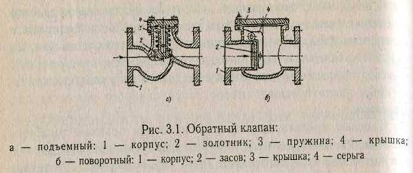
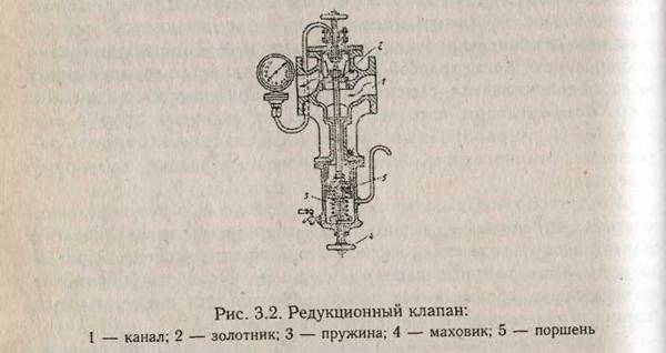
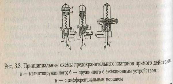
Periodically the pipelines are subject to external inspection and hydraulic testing. At external survey the condition of welded and flange joints, glands is determined, slopes, deflections, durability of load-bearing structures are checked. A hydraulic test is performed with the set pressure, depending on the material of the pipeline. results hydraulic test are considered satisfactory if the pressure has not dropped, but in welded seams, pipes, valve housings, there are no signs of ruptures, leakage or fogging.
3.2.12. SAFETY IN OPERATION OF CYLINDERS Cylinders should be calculated and manufactured according to the regulatory documentation agreed with the State Security Inspection of Ukraine. Cylinders should have valves that are tightly screwed into the holes in the neck or into the filling-filling nozzles of special cylinders that do not have a neck. Cylinders for compressed, liquefied and dissolved gases with a capacity greater than 100 liters must have a passport.
For cylinders with a capacity of more than 100 liters, safety valves must be installed. In case of group installation of cylinders, it is allowed to install one safety valve for the whole group of cylinders. Cylinders with a capacity of more than 100 liters, which are installed as storage tanks for liquefied gases used as fuel in cars and other vehicles, except for the valve and safety valve, must have a maximum level indicator. These cylinders also allow the installation of a special filling valve, a valve for taking gas in the vapor state, a gas level indicator in the cylinder and a drain plug.
The side connections of the valves for cylinders filled with hydrogen and other combustible gases must have a left thread, and for cylinders filled with oxygen and other non-flammable gases, the right-hand thread. Each valve cylinder for explosive flammable substances, hazardous substances 1 and 2 classes of hazard in accordance with GOST 12.1.007 should be provided with a plug, which is wound on the side
The socket. Valves in oxygen tanks must be screwed in
The use of sealing materials that exclude sunbathing
Oxygen medium.
On the upper spherical part of each metal cylinder, the following data must be clearly visible:
Trademark of the manufacturer:
Number of the cylinder;
Actual empty balloon mass (kg): for cylinders up to 12 l inclusive up to 0.1 kg; from 12 to 55 L inclusive - with an accuracy of 0.2 kg; the mass of cylinders with a capacity of more than 55 liters is indicated in accordance with the ND for their manufacture:
Date (month, year) of manufacture and next survey; - working pressure (P), MPa (kgf / cm2);
Test hydraulic pressure (P), MPa (kgf / cm2);
Capacity of cylinders, l; for cylinders with capacity up to 12 liters inclusive - nominal; for cylinders with a capacity from 12 to 55 liters inclusive, actual - with an accuracy of 0.3 liters; for cylinders with a capacity of more than 55 liters - in accordance with ND for their manufacture;
Stamp OTK of the manufacturer of a round form with a diameter of 10 mm (with the exception of standard cylinders with a capacity of more than 55 liters);
Standard number for cylinders with a capacity of more than 55 liters. Weight of cylinders, except for cylinders for acetylene,
It is indicated taking into account the weight of the applied paint, the ring for the hood and the shoe, if such are provided for by the design, but without the weight of the valve and the hood.
On cylinders with a capacity of up to 5 liters or a wall thickness of less than 5 mm, passport data can be stamped on a plate soldered to a cylinder or painted with enamel or oil paint.
Cylinders for dissolved acetylene must be filled with an appropriate amount of porous mass and solvent. After filling the cylinders with a porous mass and solvent, a tare mass is knocked out on its neck (the mass of the balloon without a cap, but with porous mass and solvent, shoe, ring and valve).
The outer surface of the cylinders should be colored in accordance with Table. 3.2.
|
Name of gas |
Color of cylinders |
Text of the inscription |
Color of the inscription |
Band Color |
|
Argon crude Argon technical argon pure Acetylene Butylene Naftogaz Nitrous oxide Oxygen Oxygen medical Hydrogen sulfide Sulfuric anhydride Carbon dioxide Phosgene Chloro Cyclopropane Ethylene All other combustible gases All other non-combustible gases |
Dark green Black Brown Gray Black Protective Aluminum Aluminum Aluminum Aluminum Protective Orange Purple |
Argon crude Argon technical Argon pure Acetylene Butylene Naftogaz Compressed air Helium Nitrous oxide Oxygen Oxygen medical Hydrogen sulfide Sulfuric anhydride Carbon dioxide Cyclopropane Ethylene Name of gas Name of gas |
Brown 2 red 2 yellow Green |
Exploitation of cylinders.Workers who service cylinders must be trained and instructed in accordance with the I current regulatory documentation. When operating cylinders it is prohibited to fully use the gas that is in them. The residual gas pressure in the cylinder should not be less than 0.05 MPa (0.5 kgf / cm2).
The release of gases from cylinders in containers with a lower operating pressure should be carried out through a reducer designed for the gas and painted in the appropriate color. Camera low Pressure The gear unit must have a pressure gauge and a spring safety valve adjusted to the corresponding permissible pressure for the container into which the gas is supplied. If it is impossible to use gas in the cylinders because of the failure of the valves, the latter must be returned to the filling station. Filling of cylinders in which there is no excess pressure of gases is carried out after preliminary testing.
Cylinders with gases can be stored both in special rooms and outdoors, in the latter case they must be protected from atmospheric precipitation and sunlight. Joint storage in one room of cylinders with oxygen and combustible
Gases are forbidden.
Cylinders with gas that are installed in the premises should be at least 1 m away from the radiators and other heating devices and furnaces and not less than 5 m from heat sources with open fire.
Cylinders with toxic gases must be stored in special
Indoors.
Filled cylinders with shoes mounted on them should be stored in an upright position. To prevent falling, the cylinders should be installed in specially equipped sockets, cages or protected by a barrier. Cylinders that do not have shoes, can be stored horizontally on wooden frames
Or racks.
When storing cylinders in stacks, the height of the latter is not
Should exceed 1.5 m. The cylinder valves must be facing
One way. Warehouses for storage of cylinders filled with gases,
Should be single-storey, with light-type overlappings and not have
Attic rooms. Walls, partitions, warehouses for
Storage of gases must be fireproof at least level II
Fire resistance; windows and doors should open out. Glass on
Windows and doors must be matt or painted in white
Colour. The height of the storage space for cylinders should not be
Less than 3.25 m from the floor to the bottom of the protruding parts of the cover. Floors
Warehouses should be flat with a non-slip surface, and warehouses
For cylinders with combustible gases - with a surface of materials,
Which exclude sparking. Lighting warehouses for
Cylinders with combustible gases must comply with the standards for
Explosive.
Warehouses for cylinders filled with gas must have natural or artificial ventilation in accordance with the requirements health standards. Warehouses for cylinders with explosive and flammable gases must be located in the lightning protection zone. Transportation of gas-filled cylinders should be carried out on a spring or on a truck in a horizontal position, necessarily with gaskets between the cylinders. As a gasket can be used a wooden beam with cut out jacks for walloons, as well as rope or rubber rings with a thickness of at least 25 mm (two rings per cylinder). Cylinders during transportation must be turned with valves in one direction with the caps on them. Cylinders can be transported in special containers.
3.2.13. SAFETY IN OPERATION OF CRYOGENIC EQUIPMENT INSTALLATIONS
Dangerous and harmful factors when working with cryogenic
Fluids
Cryogenic products are substances or a mixture of substances at cryogenic temperatures of 0-120 K. The products of low-temperature air separation are classified as the main cryogenic products: nitrogen, oxygen, argon, neon, krypton, xenon, ozone, fluorine, methane, hydrogen, helium.
Dangerous and harmful production factors arising when working with cryogenic products are divided into general and specific, specific to certain cryogenic products.
The general dangerous and harmful production factors are:
Low temperature of cryogenic products;
Spontaneous increase of pressure of gaseous and liquid Cryogenic products during their storage and transportation.
General and harmful production factors are dangerous:
Burns of open areas of the body and eyes due to contact with objects that are at cryogenic temperatures
And when low-temperature vapors of cryogenic products hit the lungs;
Freezing due to deep cooling of body parts in contact with cryogenic products;
Destruction of equipment due to thermal deformations and coldness of materials;
Leaks due to depressurization of equipment due to unequal thermal deformation of parts;
Explosive destruction due to increased pressure as a result! effervescence or evaporation of cryogenic liquids in closed volumes when operating modes change or due to natural heat inflows.
Specific, dangerous and harmful production factors when working with cryogenic products depend on the individual characteristics and physico-chemical properties of the cryogenic product.
Methods for safe handling of cryogenic liquids
Protection from burns and frost.When working with cryogenic liquids and gases, measures should be taken to prevent personnel from contacting cryogenic products and with surfaces that are at low temperatures. To this end, apply sealing, insulation, fencing equipment, warning labels and painting.
Work related to open drain, overflow, when it is possible to spray liquid droplets, should be carried out in protective sleeves filled with sleeves and zash, eyeglasses with side shields. Outer clothing should be tightly closed, and trousers should cover the shoes.
When transfusing liquid cryogenic products from Dewor vessels, a leaning support should be used in which the vessel must be firmly fixed. When transfused into vessels with a narrow neck, it is necessary to use funnels, which ensure the escape of gas from the filled vessel.
Protection against the effects of thermal deformations.To protect against thermal deformation, various compensators are used, materials with the same coefficients of linear expansion are used. Especially dangerous are sharp heating and cooling, when there are significant uneven temperature fields in the material.
Protection against overpressure during evaporation and heating of cryogenic products.As a result of boiling or evaporation of cryogenic liquids, when the operating conditions change or due to natural heat influxes in closed volumes, pressure can be increased. Large masses of gas can be released by boiling a so-called "superheated liquid," at a given pressure when the liquid is shaken or the container is depressurized.
On the vessels and on the pipelines with cryogenic liquids, which on both sides are limited by the stop valves, safety devices (valves, membranes) must be installed.
Protection against air condensation on non-insulated surfaces of cryogenic equipment.Condensation of atmospheric air at a pressure close to 0.1 MPa occurs at temperatures below 79 K. Such temperatures are most often when working with liquid nitrogen, hydrogen, helium. The place of condensation is the sections of cryogenic pipelines or apparatus on which insulation is impaired. The termination of condensation is achieved by restoring the insulation on the damaged area. As a temporary measure, it can be recommended that the stripped area is blown with nitrogen.
Requirements for premises.If the concentration of oxygen in the atmosphere can exceed 23% of the volume of the room, then the premises should have combined extract and input ventilation. In this case, the fence should be carried from below, and the inflow - from above. The ventilation is equipped with remote or automatic switching on and off, duplicated by manual control in the room.
For the flow of oxygen in the room, channels along the walls or under the floor with a slope of 1: 100 or 1: 500 towards the emergency ventilation system should be provided. Under the sampling device is equipped with a concrete inflow for the drain of liquid oxygen in emergency straits towards the intake device for emergency ventilation.