Simple automation for the pump. Well pump control unit: Comfortable water supply
Automation for submersible pump
Drilling a well into the water in the suburban area, usually begin to arrange it, because the water should be raised from the depths and fed into the house. But it's not enough to just bring it down, you need to build an automatic water supply system and set it up correctly. From the setting depends on its service life, as well as the life of the deep pump. Perhaps you did not know, but often a downhole pump breaks down due to frustrated automation.
All the settings and settings are handled by specialists from the drilling organization and you, as an ordinary dacha person, do not necessarily have to spend time on it. But if you are interested in knowing how automation works for a well with a submersible pump, do you need a hydraulic accumulator, what are the causes of system failures, etc., now we will tell everything.
Automation for a pump with accumulator
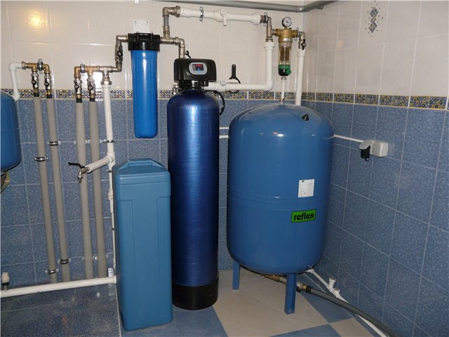
The most common variant of pump automation is with the hydraulic accumulator, because it does not require large financial costs and completely solves the issue of water supply. The accumulator tank is a container, inside which there is a rubber membrane, this tank is put in caisson or in the house.
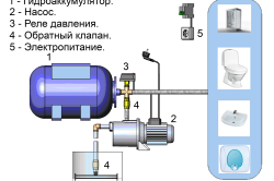
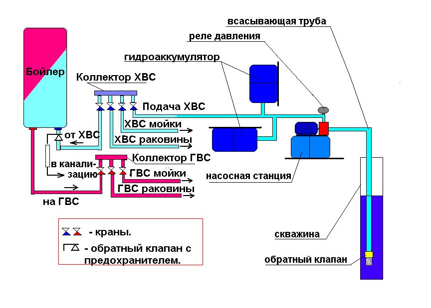
The scheme of automation for a well with a hydraulic accumulator looks like this: the pump pumps water from the well into the tank, thereby stretching the membrane until the pressure rises to the set value, then the pressure switch opens the contacts and the pump shuts down. Further, the water was withdrawn, the pressure in the system began to fall, but the pump was turned off. As soon as the pressure has dropped below the preset level, the pressure switch closes the contacts and the pump starts to pump water again.
And so on ad infinitum.
- You need a place for the accumulator tank.
Membrane tank 100 liters or 50 liters
The most popular volume of the tank is 100 liters, but there are also more compact - 50 liters. Part of the truckers refuses to put a 100-liter hydroaccumulator tank because it's 50 liters seems to be sufficient volume. Let's find out the better membrane tank per 100 liters:
- Since a rubber membrane is installed in the tank, in which water is contained, and behind the membrane, air, the useful volume of the tank is a maximum of 70%.
- Of these 70%, the tank can not give out all the water, because it needs to maintain pressure in the system. It will let fall pressure, for example, 1 atm., And this can be about 30 liters.
- The larger the volume of the hydroaccumulator tank, the less will be included submersible pump for dewatering, which means your pump lasts longer.
Automation for a pump without a hydraulic accumulator
It is possible to build automation without a hydraulic accumulator, but for this you need a submersible pump with a frequency converter. In such cases, still put a small tank of liters to 5, so that the water went right after the opening of the crane, because the pump has delays when turning on, even if it is second.
Normal borehole pump can be either switched on or off, while a pump with a frequency converter can adjust to the current water consumption mode and give out more or less water. Having opened the tap, the pump will turn on, and it will pump water, opening two cranes, will swing more and so on until it reaches its maximum.
A vivid example of such a pump is Grundfos SQE, as well as three-phase pumps , to which you can buy a control unit with a frequency converter.
- Do not put the accumulator tank.
- The price of a pump with a frequency converter is much higher.
Automation at low well production rate
Sometimes there are wells, the flow rate of which is not able to provide the house with water and in order to get out of this situation, it is necessary to establish, somewhere in the basement, a large water tank. In this case, the automatic water supply system will work not by pressure, but by level.
The scheme of its operation looks like this: a borehole pump pumps water into a tank, and in it a float, when the float rises to the set level, it closes the contacts, gives a signal to the control unit, which turns off the pump.
The same is true in the opposite direction: the water level has fallen to the set value, a signal is sent to the control unit and the deep pump is turned on. It's simple.
Instead of the float, the lower and upper electrodes can be used. As soon as the water floods the upper electrode, it sends a signal to the control unit, which will shut off the submersible pump. The same thing in the opposite direction: the level fell below the second electrode, the control unit includes a downhole pump.
Pump water from the tank into the system will be the second pump.
Reservoir for a well
Perhaps the worst solution is to use a container with water somewhere in the attic, in the form of a kind of receiver. It will stand at a height of 3 meters from the tap, and the water pressure will be 0.3 atm. No technique will work, and you normally can not use the water normally. To pressure was in order, you need to put a water tower Rozhnovsky to a height of 20-30 meters. Naturally, in the suburban area of the Moscow region this is unrealizable and there is no need for this.
Causes of failure of well automation
Automation should always be adjusted and monitored because the pressure in the accumulator tank is discharged over time, through micro-slits, through anything, but the pressure will inevitably fall. Then, a frequent start of the submersible pump with accumulator or something else begins.
Drilling company prescribes the point about the need for periodic maintenance of the system. But since it costs money, no one services anything, and exploits until problems appear or the pump burns out.
Due to a system breakdown, the pump may not turn on in time. For example, all the water had left the tank, and the submersible pump had not even turned on, the water stopped flowing. Then the pump turns on and refills the tank, at this time everything is working fine, until again the water completely merges out of the tank, and so on in a circle. That's why the water from the well is jerking. Another reason for the water jerking is an improperly matched pump, the performance of which is slightly higher than production rate.
Also, after a while, the contacts on the pressure switch burn out due to constant switching and at one point it just will not turn on. The problem is solved by replacing the pressure switch with the same new one.
If the automation with the control unit, then there are a lot of reasons and without specialists from the service center, it's better not to go there.
- Automatic block
- Advantages and disadvantages
- Station diagrams
- Location:
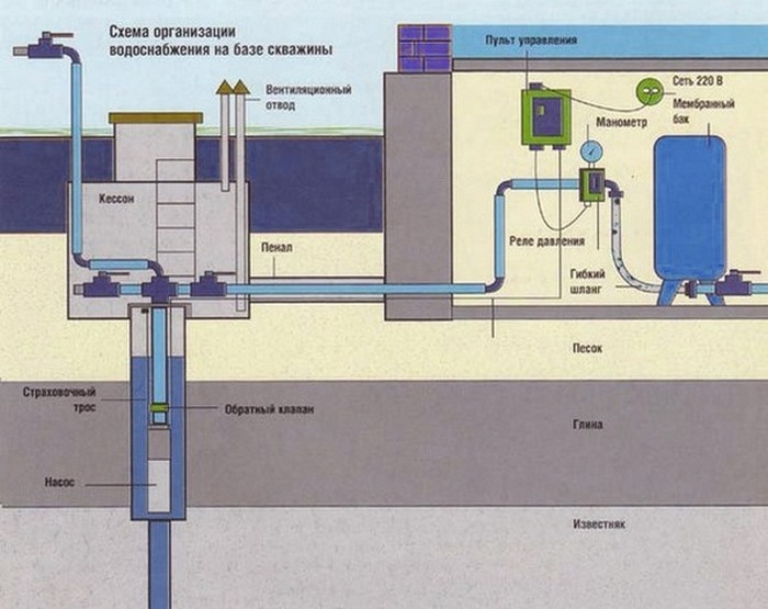
Water supply suburban area can be provided by various methods, but today a well or well is more often used. In this case, you can get an uninterrupted supply of clean drinking water, do not depend on the whims of the central water supply. It is the well that is the main source of water supply when the site is far from the city or there is no way to use the centralized water supply. In order for the well to work, it is necessary to provide for the presence of a pump, filter, accumulator, special automation is used for control. An efficient and efficient pumping station is created, which ensures uninterrupted supply of water.
Such stations are now delivered in ready-made form, but you can assemble it yourself. Automation for the pump is even more preferable, since it is possible to select the equipment for the specific needs of the well, rather than changing the factory settings or changing the ready-made nodes. This is costly, not always effective and requires additional financial resources. A separate selection of equipment allows you to save money, it is possible to choose exactly what is suitable for a particular pump and well.
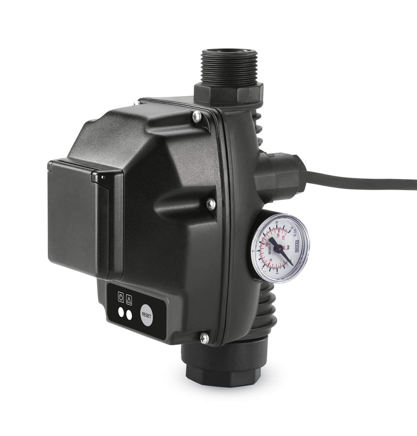
Automatic block
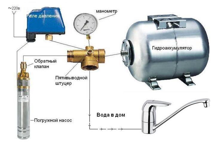
Automation for a well with its own hands includes such necessary elements:
- Distributing the collector, which supplies water to the necessary points in the house and on the site.
- Relay, which regulates the operation and on / off of the pump itself when certain pressure levels are reached. Such relays can be supplied with pre-configured factory settings, but if necessary they can be entered manually, based on the values for a specific pump.
- A pressure gauge showing the working pressure.
Today the market has a large number of ready-made control units, but you can assemble the station yourself. In addition to the listed units, it is desirable to add a dry-running sensor that will shut off the pump if water stops flowing into it. This allows you to prevent damage to equipment, the engine will not burn out if the well dries up suddenly or the aquifer changes its characteristics. For pumping station it is recommended to install such nodes:
- A unit for regulating the power of the pump, which allows maintaining the necessary operating conditions.
- The protection system, which includes 3 nodes at a time: the already mentioned dry-running sensor, the burst pressure sensor, the pump overload protection.
Back to contents
Advantages and disadvantages
You can buy already finished equipment, which is different and its advantages and disadvantages. Of the pluses it should be noted:
- The automatic control units are already designed to work with a certain type of equipment.
- There is no need to independently look for nodes, collect them in one block, synchronize the work.
- Such control provides a smooth start, the pump capacity changes in the established mode, there is no need for constant supervision of the system.
Of the minuses, it should be noted that the cost of the finished unit is high, all nodes can be selected at a more affordable price. It is possible to choose exactly the equipment that is better suited for the chosen pump model. For such equipment, a hydraulic accumulator is required. For the well, a certain input pressure of 0.3 bar is required, since vibrating pumps too much difference is not intended.
It is for this reason that many people prefer to assemble the control units themselves. Today, it is not so problematic to purchase separate units, pump manufacturers immediately offer certain systems for automatic control and monitoring. This allows you to accurately assemble the automatic unit, saving considerable financial resources.
Back to contents
Station diagrams
When the pump is installed, it is necessary to immediately ensure that the control equipment is installed, i.e. a pumping station, which normally does not take up much space. Such schemes of automation are many, today you can buy already ready. But not always factory schemes are suitable for a specific case. It can happen that you have to buy certain nodes or reconfigure them, and this is an unnecessary waste of time, money.
Among the schemes that are used for the automation of a downhole pump, it is necessary to note the following:
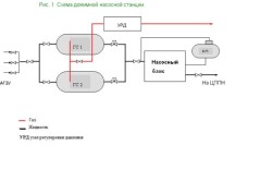
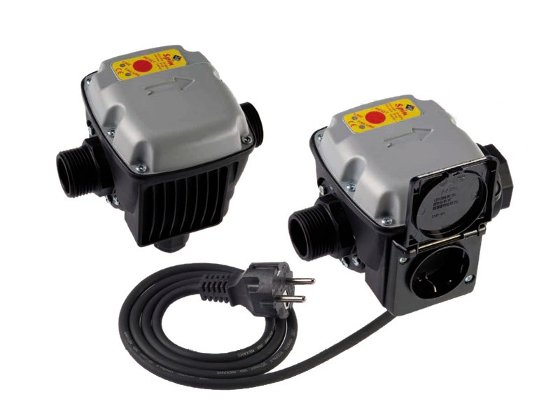
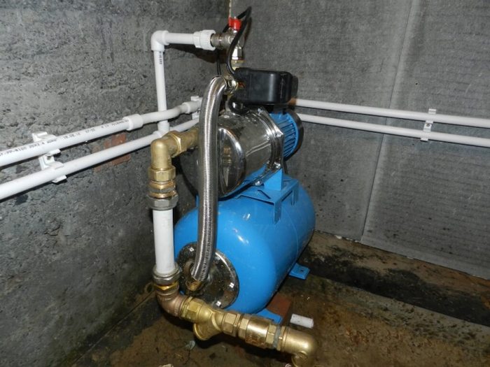
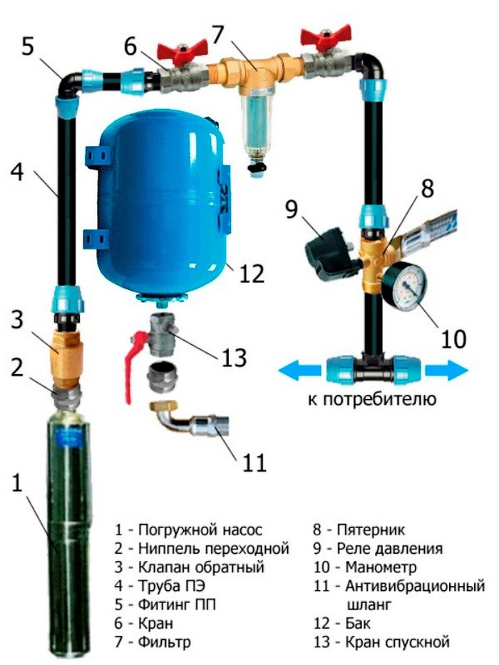
- The most common is the scheme, when all the nodes and elements are assembled in one place, often it is also called the "pump on the barrel." Such automation is compact, it does not take up much space, it is great if the site is not very large and there is a need for space saving. The water for the accumulator is supplied by a special flexible connection or by a pipe. This means that the hydraulic accumulator and the pump itself can be installed in various places. Can be used deep-well pumps, and automatic control is carried out from the surface, providing excellent quality and performance of the system.
- It can also be used such an automation system, where a station with control and monitoring units is located directly on the accumulator. In this case, it is recommended to connect the system manifold to the pump supply pipe. This makes it possible to obtain a so-called distributed station. The pump is in this case in a well or borehole, and the accumulator itself is housed in a house, where necessary requirements for such equipment are provided.
- The distributed pumping station with the automation unit can be more perfect. It is located near the collector cold water, where the necessary constant pressure. The accumulator is placed under the bathroom in the bathroom, and the pressure water pipe itself will leave directly from the pump. The pump in this case is used superficial, it is mounted near the mouth of the well or well. But it is possible to apply also submersible which do not make any noise at work. The pump is not on the surface, but works under the surface of the ground.
For home use autonomous water supply it is important stable head online. This will reduce the inefficient operation of the pump. Also, during the opening of the tap, water will be delivered immediately, without any delay.
It is impossible to prevent the occurrence of water hammers in the water supply system. Such phenomena destroy not only water supply system, but also adjacent units, such as a boiler heat exchanger or dishwashers. To get rid of any negative factors, you need to know how to connect the hydraulic accumulator to the submersible pump.
Design of hydraulic accumulators
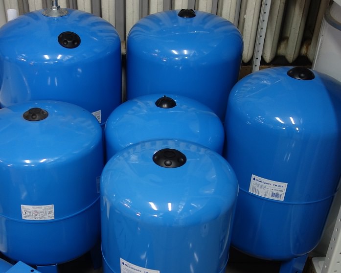
As a rule, the exterior of these devices is painted blue or blue in order to differ from expansion tankshaving an outer red surface. The constituent parts hydraulic device are such elements:
- metal housing;
- membrane of rubberized material;
- lid with a valve for filling the cavity with liquid;
- nipple unit used for pumping compressed air;
- legs with holes for fixing bolts, providing stability on an even platform.
Hydro accumulators are called metal hollow vessels that have a membrane inside, fixed on the inside of the body. It is a reservoir of water. The cavity of the membrane is filled with either pure air or a mixture of inert gases. In order to know how to choose the right accumulator for the well and water supply, it is necessary to take into account that the working pressure inside the filled membrane is about 1.5 atm. This value is maintained throughout the life of the device.
Structure diagram
Before connecting the accumulator to the system, it is filled with inert gas or simple air. This operation is performed using a standard car pump. If the value has been transferred, it is sufficient to bleed excess air through the nipple.
When water enters the tank, the pear rupture is prevented. It also contributes to the regulation of systemic pressure.
There are three most popular groups of hydraulic accumulators:
- Cold. Used on highways with cold water. Effectively works in protection against wear and during smoothing of water hammers.
- Hot. Performs all the same functions as the cold, but is able to withstand an aggressive temperature environment.
- For heating. This type is relevant only in heating systems closed type.
Battery operation
The schematic of the connection of the accumulator includes a chain from the water supply pump, the main pipeline and the liquid accumulator itself. The water supply is carried out directly inside the rubber membrane, located in the cavity of the metal product. The procedure is terminated after the parity is reached in the pressure values.
Typically, the values on the manometer in this situation are 1-3 atm. After entering the operating mode of the generator, the automation switches off the pump.
When a consumer opens a tap or launches a dishwasher, the water accumulated in the battery cavity moves into the water pipe, because there the pressure is less than in the accumulator. This happens gradually, and at a stage when the pressure level in the cavity has reached a certain set point (the manufacturer or the consumer of the product is setting up the unit), the relay that connects the make-up water pump turns on. Through it occurs the next filling of the membrane with water. Such cycles occur almost constantly. Before setting up the accumulator and the relay, it is worth to read the detailed instructions.
Being interested in how correctly to connect a hydroaccumulator for water supply, many forget about the importance of its volume. The large dimensions of the tank allow less frequent use of the pump, because with little water flow, there is no recharge every time. The pressure drop between the maximum and minimum values is large enough.
Application of surface pump
To know how to properly install the accumulator in the water supply system, it is worthwhile to study the step-by-step ancillary instruction:
- It all starts with checking the air pressure inside the gas cavity in the battery. The value must be brought to such a level that it is by 0.2 ... 1.0 less than the minimum set by the manufacturer of the relay.
- Work is carried out with a fitting having 5 outputs, since a hydraulic accumulator will need to be connected to a pressure gauge, relay, pump. The last output is relevant for connecting the water pipe.
- The connection for the procedure is connected to the tank. To do this, you need a rigid hose that has a bypass air valve in the design.
- With the necessary force, tighten the remaining devices so as not to break the threads.
After installation, the module must be tested for high pressure to identify possible leaks in the compounds.
Before adjusting the accumulator and connecting the relay responsible for pressure regulation to it, you will need to familiarize yourself with the installation marks on the latter. Contacts are signed as "network" and "pump". It is undesirable to make mistakes when connecting an electrician, so as not to disable the unit.
Since the vessel operates under high pressure, maximum sealing in all threaded connections. For this purpose, the use of FSM tape or the use of technical flax. They are able to hold the connection up to several atmospheres, which is typical for domestic hydraulic systems.
Model Selection
On sale there are models of household accumulators from 24 l to 1000 l. It is necessary to start from the way to ensure the flow of liquid, and also whether the system is used for irrigation.
Typically, the capacity of 24 is enough for the needs of two people. In calculation the kitchen, a toilet and watering of a small site undertakes. At higher requirements, it is recommended to use a cavity of 50 liters. In this case, the number of consumers is calculated. Capacity can be changed at any convenient time to a large volume, because the connectors in most models have the same threaded parameters.
Use of pumping stations
If it is not possible to collect individual elements in a chain, you can purchase a pumping station. This fully assembled unit, which includes:
- surface centrifugal pump;
- pressure meter;
- automatic relay.
When connecting the accumulator it is necessary to completely de-energize the equipment. The working pressure is 2-2.5 atm, after which injection it is necessary to check the equipment for leaks and operative switching.
Why do I need one more accumulator?
Additional hydraulic accumulator provides the most optimal operating mode. The fact is that in a centrifugal pump, as well as any others, when turned on more often 6-7 times per minute breaks down 3-4 times faster. The built-in accumulator is designed to equalize the pressure difference between the switched on and off unit, while the additional accumulator will compensate for the difference, stabilize the operation of the equipment at frequent switching on and increase the pressure in the system.
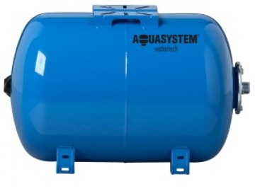
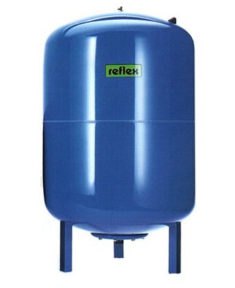
Vertical or horizontal?
The design of both the vertical and horizontal accumulators is absolutely identical, so the choice of any of them is a purely personal matter. Which one is suitable for certain conditions, and it must be installed. With a small amount of free space, the vertical one is preferable.
Where do they buy pumps, pumping stations and components?
All the elements necessary for water supply are sold in construction and specialized stores. Also, they are fashionable to order online, but carefully check the operability of the equipment.
Be sure to complete the warranty. Complex devices, including surface and deep pumps, often fail for reasons beyond the user's control.
VIDEO: What for in a water supply system a hydroaccumulator?
The operation of underground water intake makes comfortable not only its proper arrangement or competent suspension of a downhole pump. Of decisive importance is the connection option, which will ensure the best use of its capabilities and maximum control over the work, preventing the emergence of force majeure.
In this article we will describe what the control unit is downhole pump, and we will consider, what variants of connection of the pump equipment are most rational.
Automation for the pump
Sweat by the term "automatics" means a set of sensors and relays that monitor the power part of the equipment and various types of its protection. The main goal: to protect the pump and its motor from influences that can disrupt the mechanism, as well as systematize its operation.
Two schemes for controlling pumping equipment have become widespread. One of them includes the introduction of a storage tank (a hydraulic accumulator (see)) into the water supply network.
In this case, the control is carried out according to the water level in it. The second scheme involves controlling the pressure directly in the discharge line.
Monitoring by liquid level
The scheme with accumulator tank is focused on the timely accumulation of water in the reservoir. From it, it is fed to the collector or an additional (second-lift pump). By the way, there can also be several tanks - it depends on the length of the pipeline route or the number of storeys of the building.
So:
- The system looks like this: a special electrode is installed inside the tank - the so-called level sensor, and it, by means of the relay, tracks the lower and upper water levels. At the minimum level, the pump is turned on and the tank is filled until the water reaches the upper mark. The required levels are set by the sensor before connecting the network.
- These schemes are used not only in private water pipelines, but also in village water supply networks that feed from the general. Electrode sensors are installed in large tanks, and hydroaccumulators for household use are equipped with float switches.
![]()
- This option is not as reliable as the electrodes, but its use is due to a small working resource. Therefore, in such systems, an emergency drain is provided - in case the automation does not work. Float sensors are often equipped with pumps themselves, for example: drainage, because they are immersed in a storage well, the level of fluid in which, too, need to be monitored.
- In general, the connection scheme with the storage tank is completely reliable, and ensures the stability of the operating mode of the pumping equipment. In large wells, where the role of a storage reservoir plays water tower, the pump supply is determined by the depth of the intake and the height of the tower.
- In this case, a one-time water injection cycle is equal to the sum of the volume of the reservoir and the volume of the current flow. Thus, the probability of short-term pump starts is excluded, which significantly extends the life of the pump.
- This also applies to small water supply systems feeding from shallow water intake, for example: mini-wells (). They often use household pumping stations for water supply, which are an assembly with a pump, a membrane tank and automatic assemblies.
And here, as you understand, the main condition for the stability of the system is not the price or brand of pumping equipment, but its competent selection for the parameters of the system, and, of course, the qualified commissioning.
Control over the pressure in the pipeline
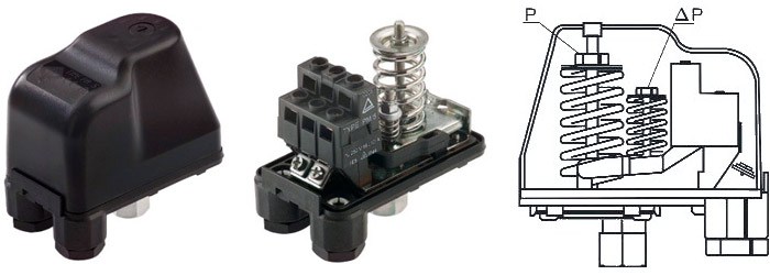
In this scheme, the pressure sensor is the main one, and the pump unit is directed by its commands. The relay is placed on the pipeline, and adjusted to two main indicators: the pressure at which the pump should start, and the upper boundary, after which it should be shut off.
- The connection variant, which you see in the photo below, is typical for systems with an individual well, and is often combined with the first option, where a membrane tank is present. At low volumes of water flow, it is much easier to maintain the necessary pressure in the network, and to minimize the possibility of water hammering.
- Of great importance is the correct adjustment of the sensor, which would correspond to the size of the tank, and the pressure characteristics of the pump. It is necessary that the specified pressure limits are within the operating range of the pump, which will reduce the frequency of its start-up. On this score, the manufacturer's instruction gives its recommendations, and when implementing the equipment in the system, they need to be strictly adhered to.
- Naturally, the pressure switch is divided into industrial and household. The former may not have a scale for setting the pressure range - they are adjusted through a pressure gauge. There are more reliable options, differing by high accuracy of adjustment, and working through an external starter.
- The type of relay is selected based on the calculated power of the network, and it is crucial when choosing automation and wiring diagrams. Household pressure sensors allow you to connect the pump to the network directly, without using complex circuits - the video in this article will acquaint you with this process.
- This is the simplest, and therefore the cheapest way to connect, but it should be noted that this is where its benefits ended. Such savings lead to reloading of the relay, which quickly fails.
- It's not difficult to replace it, although the relay also costs money. The problem is that the owner of the network, not being an expert, is unlikely to be able to restore the settings, and independently verify the mode of its operation.
And this can lead to a breakdown of the pump, with all the ensuing consequences: dismantling, repair and re-installation of the downhole pump. Therefore, when it comes to pumping equipment, the desire to do everything yourself, can be fraught.
Pump Protection Systems
The greatest danger to the pump is the voltage drop in the electrical network and engine overheating. The operating instructions for each unit must specify the rated voltage and permissible deviations.
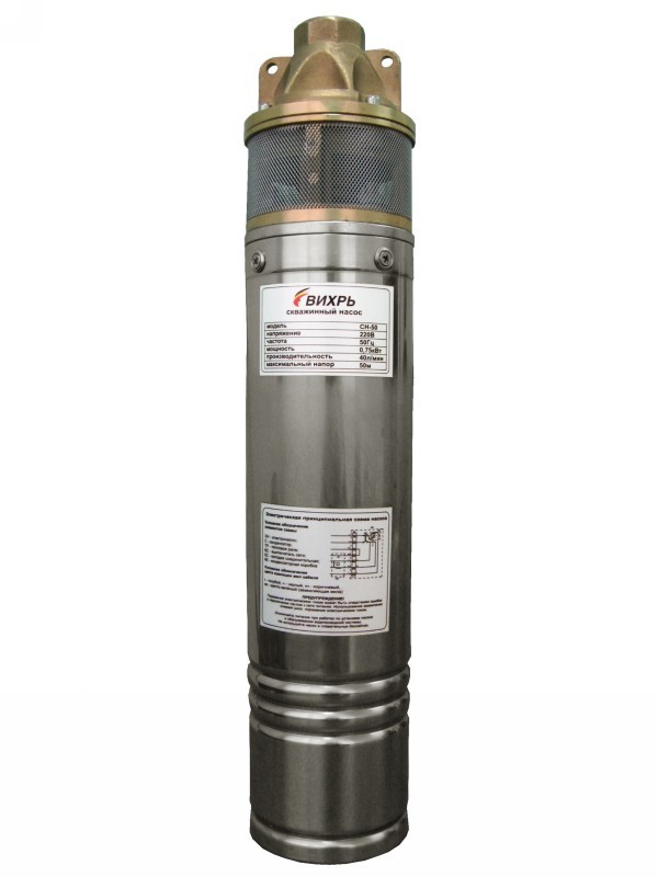
Take, for example, a well pump SN 60 85 Oasis - it has a single-phase motor designed for 220 / 230V voltage. For European manufacturers, this is the standard value, and it is adhered to as many Asian countries, as in this case, Thailand. Three-phase motors are usually rated at 400V.
Voltage and current relay
The simplest way to ensure a stable voltage is to connect a downhole pump through a transformer with an appropriate power. But this pleasure is not the cheapest: the stabilizer itself, and the electricity that it consumes, also cost dearly.
Therefore, in automatic pump control systems, household versions are meant, almost always a voltage relay is built in. If the values deviate from the specified range, it turns off the motor. In 3-phase motors, the relay can monitor the asymmetry or phase sequence.
Motor overload
From overload the motor is usually protected by an additional current thermal relay, which is adjusted in accordance with the rated current of the pump. But engine problems can arise not only in connection with power supply, but also forced work "dry".
- Such protection is equipped with all pumps, and it can be implemented in two versions. The first one is the same float sensor, mentioned above. It will not allow the pump to run if the water level has fallen to the minimum mark, which means that the pump does not face the "dry running" regime.
- In some models, such as a well pump 4 block 2 13 from a well-known Italian manufacturer, a special relay is installed along with a float. It monitors the current value, or the phase shift of the current in the motor.
- It turns out double protection: if the float for some reason did not work, and in the flowing part there is already no water, which in submersible models is both a cooling fluid and bearing lubrication - the motor is switched off by the relay command. Such an incident can happen if the pump's power characteristics exceed the flow rate of the well.
- If this is an isolated case, nothing terrible will happen, but if the pump is forced to work continuously in this mode, it will not last for a long time. So double protection never hurts. Almost all manufacturers offer for their models those or other versions of starter protection devices that duplicate the built-in protection of the pump.
- There are blocks with printed circuit boards that control through the sensors built into them - all those mentioned above. As a rule, they are adjusted to certain values, and it is already impossible to change these parameters. If the board is out of order, it's easier to buy a new device than to replace it.
- The most complex constructively are start-protection devices based on controllers, which are, in fact, microprocessors. They catch the slightest changes in the working conditions of the engine: temperature, resistance of stator windings, sequence of alternating phases - what to speak about voltage drops.
- In addition, they allow you to monitor the accounting of energy consumption and working time. Such a device can be connected to a computer and configured through it. These are costly options, and use them, mainly in tandem with a high-power pump.
- In this case, the use of such automation is economically feasible, since the cost of possible repair of the pump can significantly exceed the cost of the protective device. It is worth saying that it is unlikely to install and configure it without an appropriate specialist.
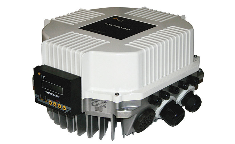
- The best protection option for a domestic pump is use. The principle of its operation is quite simple. Electricity, getting on the board, is aligned with the built-in stabilizer. The converter quickly evaluates the performance of the pump and supplies it with energy exactly as much as is required for safe operation.
- The main advantage of this device is that it controls the engine speed, not allowing to increase the speed of rotation of the rotor, and thus, protects it from overloads. And they certainly arise when the current increases.
- The inverter control unit of the pump includes not only the frequency converter, but also all the necessary complex of protective sensors. It provides not only an emergency shutdown, but also a smooth start-up and shutdown of the unit, which prevents the occurrence of water hammers in the pipeline.
And still, installing the inverter eliminates the need to introduce a hydraulic accumulator into the system - that's what you save.
Design protection of a downhole pump
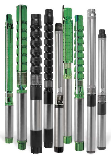
We talked about built-in and plug-in protection for pumping equipment. But there is also constructive protection, oriented mainly to reduce the negative effects of abrasive impurities in the water, on the working parts of the pump. A good example of such a solution are downhole pumps with "floating working wheels".
- Basically, these are multistage models for deep wells, with a body diameter of at least 4 inches (or 100 mm). The wheels in them are not fixed rigidly on the shaft, but can move along it, from one directing device to another. That's why they got their name "floating". Deprived of excess load, the shaft can rotate faster, thereby improving the pressure characteristics of the unit.
- The shaft itself is suspended on an axial support, and the support for the wheels is the annular beads of the guiding devices. In order to reduce friction between them, in the lower and upper segments of the working wheels are installed support washers. For their production, composite materials, which are not sensitive to friction, are used.
- The pressure created by the force and the own weight of the wheels is transferred to the axial support of the shaft, then to the guide and the body. In order to reduce the mechanical impact of sand on axial supports, manufacturers are trying to reduce the number of supports in the sections.
Thus, another positive effect is achieved: additional space appears in the cavity of the working chamber, which makes it possible to increase the number of stages, and accordingly, the power of the unit.
Today it is difficult to imagine even vacation home without a water supply system. However, in addition to pumping equipment for a well or well, in some cases it may be necessary to install a hydraulic accumulator. This device is used in the event that after lifting from the well water can not be delivered to all points of draw-off. The accumulator helps to regulate the water pressure in the water supply system. There are different schemes for connecting the tank to the water supply network. The choice of this or that circuit depends on the pump used. In this article, we will consider the scheme of connecting a hydraulic accumulator to a submersible pump installed in a well or well.
Hydraulic tank construction
The hydraulic accumulator is a metal container of cylindrical shape with a rubber pear inside it. This pear performs the functions of the membrane. In fact, a tank is a link in the water supply system. It is able to accumulate a certain volume of liquid and create the necessary water pressure in the pipeline. Due to the fact that the required pressure is created in the system, efficient operation of sanitary devices, washing and dishwashers, as well as supply of liquid to the upper floors of the residential building and to the most remote points are ensured.
The hydroaccumulator itself consists of the following components:
- membrane in the form of a rubber pear Is an elastic product that is attached to the inlet of the tank and is located inside the housing. In the neck of the tank is installed a flange with a flap;
- metal case on legs Is a sealed tank that can cope with working pressure from 1.5 to 6, and sometimes 10, atmospheres;
- nipple with protective closing mechanism is located on the back of the case. This device allows you to pump air into the space between the rubber bulb and the walls of the body.
In addition, to operate the entire water supply system with a hydraulic tank, a pressure switch is required that allows maintaining a given pressure in the system and controls the start and stop of the submersible pump, and check valve.
To fix the rubber pear to the body a special flange is used. In its design there is an inlet branch pipe. The internal structure of this tank is designed so that there is air between the membrane and the walls of the housing. It must be under a certain pressure, which is injected into the chamber by an automobile or bicycle pump. This air not only helps maintain the necessary pressure in the water supply system, but also counteracts the overextension of the pear into which water is pumped by means of a submersible pump from a well or well.
All hydraulic accumulators can be divided into several types:
- units designed for working with cold water supply systems;
- devices for pipelines with hot water;
- expansion tanks for heating systems.
In this article, we will look at the connection diagram and how the hydraulic tank works for cold water systems. This tank is designed in such a way as to accumulate the necessary volumes of water and ensure the supply of liquid to the points of water distribution. Such equipment allows avoiding water hammers and protecting the borehole pump from frequent switching.
Principle of operation
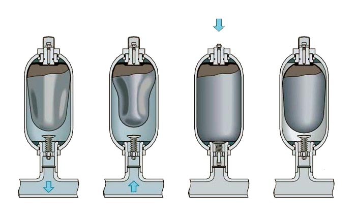
The scheme of the hydraulic tank after its connection to the water supply system is as follows:
- By means of a submersible pump, water is pumped from a well or well to a rubber bulb of the tank.
- As the water is injected, the air pressure in the chamber between the walls of the body and the rubber pear is increased by stretching the membrane with water. When it reaches the maximum set on the relay, the contacts open and the pump shuts down.
- At the same time, you can continue to use water due to the fact that the membrane pushes it to the point with an open tap, household appliances or a sanitary fixture. As the volume of liquid in the rubber pear decreases, its walls are less pressured by the air in the chamber and the pressure gradually decreases. When it reaches the minimum set on the relay, the contacts close and the pump starts working again and pumping water from the well or well into the tank.
- Then the cycle repeats.
Important: the frequency of launch of downhole pumping equipment is directly related to the volume of the rubber pear and the intensity of water consumption. That is, the volume of the tank must be selected taking into account the water requirements of a particular family, so that the pump start-up frequency does not increase, and this does not lead to its rapid deterioration.
Advantages of using a tank
- Thanks to the large capacity of the tank, you always have a supply of water, even if in the source for some reason the water is gone.
- With this equipment it is possible to maintain the necessary pressure in the water supply system, which will ensure you a uniform supply of liquid at all water distribution points.
- GibroBack reliably protects the system from water hammers.
- The service life of pumping equipment is increased due to more rare starts of the unit.
- Thanks to the injection of water into the pipeline, optimal conditions for the operation of household appliances (washing and dishwashers) are ensured.
Features of the installation
- downhole pump;
- relay;
- a pipeline for supplying water from the pumping equipment to the tank and from it to the pumping points;
- check valve;
- stop valves;
- filtering device for coarse cleaning water;
- drainage into the sewage system.
Connection scheme for surface pump or pump station looks much simpler, since the relay is installed in a block, that is, it is installed in combination with the pumping equipment, there is also an integrated coarse filter and non-return valve.
Accumulator connection
When connecting the tank to the submersible pump equipment, a check valve is always used, which does not allow water to flow back into the supply pipe and the source after the pump equipment has been disconnected. Otherwise, after turning off the pump, air from the tank will squeeze out water into the well.
The non-return valve is mounted on pump equipment before connecting all other elements of the water supply system. Further work is carried out in the following sequence:
- First, the submersible pump must be installed correctly. For this purpose, it is necessary to measure the depth of a well or a well by means of a cord with a load. After that, on a wet place on the rope you can determine the depth of submersion of pumping equipment.
It is important: the downhole pump should be lowered below the water mirror by no more than 30 cm.
- After the pump is lowered into the well, the cable on which it is attached is securely fixed to the surface at the head of the hydraulic structure.
- After this, the hose or pipeline from the pump unit to the surface is fastened to the relay using a special fitting. This choke must have five connectors.
- After that, to the connectors on the connection it is necessary to connect the water supply system going to the house, and the hydraulic tank. Also, to another connector, you need to connect the control unit of the entire water supply system.
Attention: all joints must be carefully sealed with a hermetically sealed pakli or FUM tape.
- Now you can configure the relay.
Relay Configuration
For effective and correct operation of the tank and the entire water supply system, it is necessary to correctly set the relay. Since this unit usually goes with the factory settings, this is done in the following order:
- If there is water in the system, it must be drained by opening the lower tap.
- Now you can open the cover on the relay and turn on the pump to pump water.
- At the moment of disconnection of the pumping equipment, it is necessary to record the readings of the manometer and record them.
- After that, the most remote faucet is opened and waiting for the pumping equipment to start again after a certain amount of water flows out. At this point, record the readings of the manometer and record them. Now we find the difference, taking a smaller number from a larger number. It should be equal to 1.4 bar. If your indicator was smaller, you must tighten the nut tightened on the small spring. If the number found is larger, this nut needs to be weakened.
- At the same time, if at the moment of water leakage from the farthest tap, you did not like the pressure, then it is necessary to tighten the nut on the big spring after the unit is disconnected from the mains. To make the pressure less, you need to loosen the nut on the contrary.
- After performing the setup, the system is started and tested for its effectiveness. The setting can be repeated several times until you are completely satisfied with how the water supply system works.