Managing a well pump by one's own hands. Pump control circuit
Uninterrupted water supply to a private home is a perfectly feasible task. For this, it is necessary to automate the process of replenishment of consumed water in the tanks. Since most quality automatic machines are quite expensive, and affordable for not meeting the quality requirements, you can make a homemade device for regulating water supply deep-water pump from a well or well.
Usually, water from the well enters the tank, from which it is used for the intended purpose through the connected cranes. As the liquid is consumed, the pump must automatically turn on before filling the tank and disconnect it in a timely manner, preventing overflow or rupture.
For this purpose, it is possible to use reed switches, which are a hermetic contact controlled by a magnet. Such contacts are usually used in television and radio equipment. They are reliable and durable. Reed switches usually have three switching contacts. But you can use instances with two leads, you just need to purchase two different reed switches-having normally-closed and normally-open contacts.
The pump starter is installed in a convenient place in the room. At its input voltage is supplied from the mains, and an electric pump is connected to the output contact. Inside the tank, a plastic tube is fixed to its cover, inside of which is placed a cylindrical float with a magnet fixed to it. A piece of foam can be used as a float. As the water accumulates in the tank, the float rises, and when the water level drops, it drops.

On the plastic tube are fixed reed switches - the upper, breaking network, at the maximum water level, the bottom, closing, at the minimum level. When recruiting water, the magnet on the float rises to the level of the upper reed switch. Under the influence of the magnetic field, the reed switch is triggered by shutting off the pump from the mains - the set of water stops. At the water flow, the magnet goes down to the lower reed switch, and it closes the circuit - the pump turns on and pumps water from the well to the required level. Due to the reliability of the reed switches, the system automatic regulation The work of the submersible pump works flawlessly.
Assembling the control unit for the deep pump in rooms with a low ceiling.
If the storage tank is installed in the room in such a way that the distance from its upper edge to the ceiling is too small, then the pump control unit is installed in a different way.
The float, lowered into a container, is connected by twine through a system of guide pulleys with a magnet. As a pulley, you can use bobbins from a sewing machine. A plastic tube with a magnet is placed outside the tank, in any convenient place, but so that there are no obstacles for free movement of the twine. The twine should be slightly stretched, for which you can add small weights to the magnet.

The reeds are attached to the outer surface of the tube at the correct height corresponding to the level of switching on and off the pump. In this case, the disconnected reed network will be lower than the closing one.
Control of the pump operation by a conventional switch.
In some cases, the organization of automatic pump control with the help of reed switches can be difficult or impossible. In this case, there is the option of automating the system on and off using a simple wall-mounted power switch. With its simplicity, this type of pump control is less reliable and not durable. Much depends on the quality of the electrical switch itself.

1. A float (plumbing or foam plastic) is installed in the storage tank. A non-metallic rod is attached to it, which is output to the outside.
2. The guide tube is attached to the inner walls of the tank, inside of which the rod from the float moves upward and downward with minimal resistance.
3. A magnet is attached to the rod, which will change the position of the switch contacts to "On." or "Off." In this case, the magnet must be powerful enough that its magnetic field can overcome the force of the spring resistance inside the switch.
4. On the switch key, it is necessary to securely fasten the metal plate or strong wire, the ends of which are recommended to bend in the form of whiskers-contacts.
5. The consumption container and the switch are fixed to one wall, with the switch located above the tank.
6. To connect the pump to the switch, the phase cable of the power cable is cut and the ends are connected to the contacts of the switch. The plug of the cable is inserted into the socket.
How this type of machine works.
1. When water is consumed from the storage tank, its level is lowered, accordingly, the magnet on the rod moves downward. At the moment when it reaches the level of the lower contact barb, it sharply attracts to the magnet, moving the switch to the "On" position. The pump turns on, the water begins to set.
Recently stumbled on the Internet for a video, where they embodied my childhood dream in reality. The video showed how it is possible to assemble an automatic filling device with water. All the work was very clearly demonstrated, but the scheme was not shown.
The fact is that in my childhood in the summer time I often had to water the garden and I always had ideas on automation of this process, but I could not translate my thoughts into reality. Today I will fulfill part of my dream, true, so far only theoretically.
Imagine this situation: you have a water tank at home or at home, for watering the garden or for some other purposes. In this tank you pump water with a pump. To pump water, each time you have to turn on the pump and monitor until the container is filled with water. Filling the tank with water can be very easy and cheap enough to automate.
Below is a structural picture of our device.

To automate the filling of the tank with water, we will have to slightly improve the capacity. At the top of the barrel, a rod is installed at a height not less than the depth of the container, on which two reed switches are fixed. A movable rod with a float is also attached to the rod, which moves depending on the level of water in the tank. The rod is fixed permanent magnet, to control the reed switches.
The following picture shows an example of a rod and a movable rod.

And now the most interesting: the scheme of automatic filling of capacity with water.
To implement this device we will need circuit breaker for pump protection, electromagnetic contactor for switching on and off the pump and two reed switches (magnetically controlled sealed contact) for contactor control.
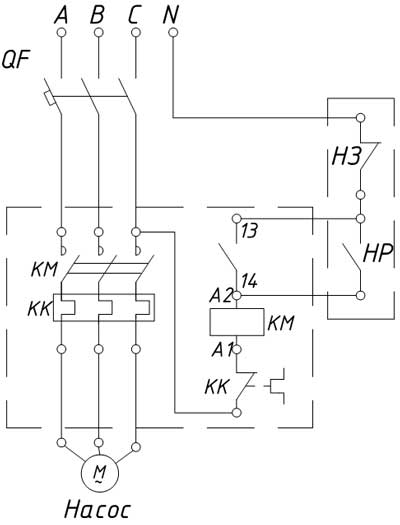
The lower reed switch should be the closing one, the upper one - the disconnecting switch. For example, we are quite fit reed switch MKS-27103, tk. it has a switching contact. For signaling the lower level in the circuit, a normally open contact is used, for signaling the upper level, a normally closed contact of the reed switch. At the moment when the water level in the tank reaches a critical value, the magnet will be located in one level with the lower reed switch, which, under the action of the magnetic field, switches the contact and thereby sends a signal to turn on the pump. After that, the float will begin to rise to the upper level, where the upper reed switch will shut off the pump.
In this scheme, manual mode is not implemented, although it should be provided in case of failure of our level gauges. The easiest way is to take a button with a latch to manually control the pump. I think how to include the button in the received scheme, you will not be difficult.
Of course, you can buy ready-made level gauges and do not reinvent the wheel, the more that industry they are produced. However, one such level gauge will cost you at least $ 30, and one reed switch MKS-27103 costs $ 2-3.
Maintenance of an autonomous water supply system includes pumping equipment and serviceability of communications, conservation of the network during a long absence, rational automatic control. The last point is easy to implement by installing a pump control cabinet in a designated area - a compact distribution station operating in several modes.
The technical filling of different models is different, since the control points have an individual functional orientation. Manufacturers offer ready-made standard schemes, but they do not always meet specific requirements, so there is such a service as manufacturing a control unit on order. First, let's try to consider common positions that unite all models.
What is the control cabinet for?
The main function of any distribution station is to organize the operation of the equipment connected to it, in this case a pump. With one control panel (which is convenient, if the distance between objects is large), effective control is carried out over the engines of drainage, submersible, downhole pumps.
The number of connected units can be different. Minimum connection - a single well or submersible pump that supplies water and provides it with the entire water supply system (heating, fire extinguishing). In addition to it, a drainage pump is connected, which is necessary for pumping out water in domestic and emergency situations.
Image Gallery


Automatic switching on / off of pumping engines facilitates the life of owners of a private house, allowing free time to spend with the family, rather than manually switching toggle switches. A few more convenient functions that can be "charged" to automation:
- control voltage in the network, necessary for the uninterrupted operation of equipment;
- protection of mechanisms from power outages and short circuits;
- monitoring the water level in the well (or other reservoir) and responding to its lack;
- fixing pressure jumps and adjusting optimal parameters (stopping the engine when a critical level is reached, starting when leveling indicators);
- remote control of downhole pumps, direct access to which is impossible;
- load sharing between several units or emergency connection of a spare variant.
As a result of centralized automatic control, the operation of pumping stations becomes more productive, and the service life of electrical equipment increases noticeably. Modern electronic systems allow you to program mechanisms and include them in a convenient mode (for example, only in the daytime).

Housing image and control cabinet layout with start-up protection equipment and automatic backup restart board without specifying a specific modification (+)
All faults are recorded, and alarms are triggered during the occurrence of an emergency. On the material side - saving energy costs and, accordingly, reducing fees for electricity.

Example of a structural automation scheme pumping station with two connected pumps (380 V), which uses a frequency-controlled electric drive (+)
Standard equipment: brief description
The presence of these or other elements depends on the number and category of pumps, narrow or wider technical capabilities, the availability of additional functions.

Pump control 3.3: Functional diagram of the device. Automatic switching-off and fixing of an emergency situation is carried out at an overload, "a dry course", change of a water level in the tank (+)
The basic equipment for most of the models offered for sale is as follows:
- Rectangular metal housing with a control panel located on the front side. The design of the panel may differ, but it necessarily contains indicators and buttons such as "Start" or "Stop".
- A switch (one or more) that allows the pump to be turned on / off manually.
- Fuses and protection elements.
- A control unit regulating the voltage of three phases.
- The frequency converter required to control the induction motor.
- Automatic control unit responsible for scheduled and emergency shutdown of equipment.
- A set of sensors showing the pressure and temperature of the water.
- Thermal relay.
- A set of light bulbs - a light alarm.
The main functions included in the control unit depend on several factors. For example, if there are 2 pumps, main and additional (backup), a program is installed that allows to include both mechanisms in turn.

Control panel for two pumps operating in standby mode. The advantage of interval switching is a uniform load distribution and an increase in the planned resource
The temperature sensor protects the equipment from overheating and operation in dry running mode (the probability of such a situation occurs often in wells with insufficient production rate). Automation stops the operation of the equipment, and in the event of safe conditions for water intake, again turns on the motor of the connected pump.
Image Gallery


Devices for protection against voltage surges, phase failure, incorrect connections protect the mechanisms and do not allow them to work in emergency mode. They adjust the network parameters, and only after aligning the indicators the equipment is automatically connected.
The overload protection functions approximately the same way. For example, there is a ban on simultaneous activation of two pumps, which leads to unnecessary costs and inappropriate use of equipment.

Virtually all debugged systems have the ability to switch from fully automated to manual control. This is necessary for maintenance, repair work, replacement of worn or burned parts
Suppose, if one pump fails, it can be unhindered to remove and send to repair, disabling the automation and using manual control.
Additional options and options
Various manufacturers include in the basic set of additional functions that enhance management capabilities. For example, the company Alta Group offers the AVR system - the inclusion of backup power in an automatic mode. The necessity of this function is explained by the fact that the work of the pumping station is part of the life support system of the house, therefore, the network must operate in a constant mode.
The principle of ATS operation is as follows: as soon as the main power supply stops, the backup network is automatically introduced. It operates until the main source resumes operation. When it is turned on, the intelligent system checks the optimality of the parameters, and only if the response is positive, it reconnects the main network. If the analysis of the tests is not satisfactory, the system will continue to work from the backup source.
Low temperatures and high humidity - the enemies of the electronic filling of the cabinet, so manufacturers offer the service of additional insulation. It is relevant for northern regions and for any areas, if the equipment is on the street.

The so-called "warm package" is a layer of insulation, laid from the inside. Thermally insulated SOUNDS are operated at a sufficiently wide temperature range - from -40ºС to +55 ºС
A fairly common addition, which allows to protect the pump motors from overload, is a soft start system. It consists in a neat, gradually increasing power supply mode, thanks to which the engine is protected from a sudden start, is put into operation slowly and carefully.
The modern dispatch function allows you to control the pump stations from a distance. Remote alarm systems are permanently connected to GPRS, radio modem or the Internet, so in an emergency the locking system immediately turns on, and the signal is transmitted to the receiving device (phone or laptop).
A convenient option that allows you to specify a specific program is possible by using a controller. It is automatically able to independently affect the operation of pumps, connect additional devices, optimize the functioning of the system as a whole.

Indication implies the location on the cover of the electronic display board with voltage and current, as well as statistical data: the number of starts, engine operating hours, the volume of water
Another good option, which provides information about stopping the system or the occurrence of an emergency, is the installation of a light alarm and a siren. In the event of force majeure circumstances, the flashing beacon lights up with a bright light, and a special sound device gives a loud repeated signal.
Samples of electronic technical connection schemes
The assembly of equipment takes place in production conditions, in the same place the basic diagrams of the pump control cabinet are made. The simplest schemes are the connection of one pump, although a set of additional devices can complicate the installation.
As a sample, take SHUN-0.18-15 (company Rubezh), designed for manual and automatic control of electric drives of the pump station. The control scheme is as follows:

On the cover of the case there are buttons for switching on / off, a toggle switch, responsible for selecting the operating mode, a set of indicators indicating system health (+)
The manufacturer implements 19 basic designs, which differ in the power of the electric motor of the pumping station - from 0.18 kW to 55-110 kW. Inside the metal case are the following elements:
- automatic switch;
- protection relay;
- contactor;
- source of backup power;
- controller.
For connection, a cable with a cross-section of 0.35-0.4 mm² is required.

The model of connecting the SHUN-0.18-15 model (for a drainage or fire pump) from the manufacturer A single-drive edge and a controller that regulates the operation of the equipment (+)
GRUNTER SHUNES, designed for drainage works, control asynchronous motors and have two control options: manual and automatic. Manual adjustment is made from the front panel of the case, automatic acts from external relay signals (electrode or float).

Triple scheme showing the operation of the cabinet for 1, 2 and 3 pumps with float automatics. If there are 2 or more pumps, a load sharing between the working and standby equipment
The principle of operation of the SHUN in the automatic mode: with a critical drop in the water level and the operation of the float No. 1, all pumps are stopped. In the normal state of the liquid level, the float No.2 is triggered and one of the pumps is started. When other floats are operating at higher levels, the remaining units are introduced.
Features of installation of control stations
All without exception, the performance of the SHUN are complex devices operating from electrical network, which means that it is necessary to install, commission, maintain and repair equipment in accordance with the manufacturer's instructions. The rules stated in the instructions different models, can differ, since the structures of mechanisms and specifications are also different.
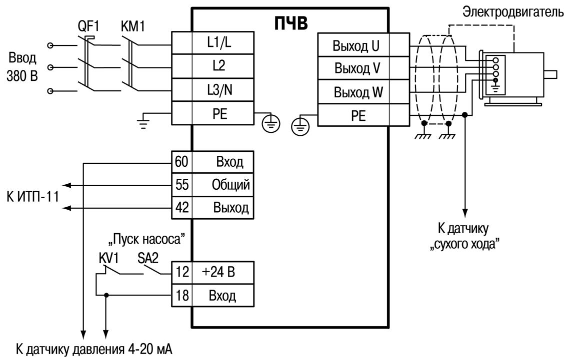
Scheme of electrical connections of the control cabinet of the pumping equipment OWEN SHUNE 1. Thanks to the use of proprietary frequency converters OWEN, energy saving reaches 35%
A few general important rules:
- Installation is carried out in a zone protected from explosions.
- The temperature and humidity in the room must correspond to the parameters indicated by the manufacturer (for example, the temperature is from 0 ° C to + 30 ° C).
- The electrical equipment must be connected by a person with a special tolerance.
- The parameters of the VCO should coincide with the parameters of the entire connected equipment.
- Installation is carried out according to the circuit diagrams given in the appendix to the instruction.
- The cross-section of the cable must match the data specified in the instruction.
Household control stations located in the private sector are subject to the same requirements as production control points. They must be installed in a dry and warm place, convenient for maintenance. It can be a basement, a specially allocated room, an annex to the house or a secure storage room.

Unlike large industrial cabinets, household models are compact and light, so most often they are available in wall-mounted versions
The connection should be made after the water supply system has been fully installed, a pressure pipeline has been installed, cables have been laid, assemblies assembled, all electrical components. Having connected the SHUN, it is necessary to check up its work both in manual, and in an automatic mode.
Technical support and service
Some companies manufacturing control cabinets declare that maintenance is not required. This is indeed the case, however, it is necessary to regularly check the control unit of the operating organization. There is a periodicity established by the manufacturer, and for the correct operation of all devices it must be adhered to without fail.
Before inspecting or replacing any parts, turn off the power and lock the equipment from being reconnected. You can independently check the reliability of the connections. A list of potential faults, like possible ways their elimination, usually also indicated by the manufacturer.

Control cabinet for borehole or submersible pump with a frequency converter for use in production boiler houses, utilities or private houses, made to order on an individual TK
For example, simple malfunction - the lamp does not light up, signaling that the system is connected to the electrical cable. There are three possible reasons: there is no voltage in the network, the circuit breaker has broken or the lamp has burnt out. Accordingly, the solution of the problem will be the supply of voltage, the replacement of a switch or lamp.
If there is a malfunction that can not be solved by yourself, you should contact a specialist service center.
Overview of popular models
Although there is a possibility of making a custom-made schooner, many companies offer basic models. Their assembly is carried out, focusing on consumer demand. We offer a brief description of cabinets that can be purchased or ordered on official websites of companies or online stores.
The Grundfos Control MP204 control cabinets are designed for automatic operation and protection of a single pump. Parameters can be adjusted in manual and automatic mode, and there are two threshold values: the first - a warning, the second - an emergency shutdown. The shutdown log with a list of reasons for the response is stored in memory.
Specifications:
- Voltage - 380 V, 50 Hz
- The power of the motors of the connected equipment is from 1.1 to 110 kW
- Temperature range - from -30 ° С to +40 ° С
- Degree of protection: IP54
The advantage is the possibility of CIU data transfer and parameter adjustment via Grundfos GO.
Pump unit control stations (STS) from NPO STOIK. Designed for automatic control of submersible, borehole, drainage pumps, capable of serving from 1 to 8 connections.

A sample of the cabinet version of the SUH 30 kW in a metal hinged case with a soft starter Aucom and a frequency converter Delta
Specifications:
- Voltage - 380 V, 50 Hz
- The power of the engines of the connected equipment is from 0.75 to 220 kW
- Temperature range - from -10 ° С to +35 ° С
- Degree of protection: IP54
Among the basic functions - automatic activation of ventilation, if the temperature inside the cabinet rises above the norm.
Multifunctional cabinets of the Grantor brand are designed for maintenance of circulation and drainage systems. Possible modes of operation: circulation and drainage by an analog sensor or by a pressure switch. Two variants of the algorithm of operation assume joint or alternate activation of pumps.
Specifications:
- The voltage is 1х220 V or 3х380 V, 50 Hz
- The power of the connected equipment engines is up to 7.5 kW per motor
- Temperature range - from 0 ° С to +40 ° С
- Degree of protection: IP65
In the event of an emergency situation and breakdown of the pump motor (due to short circuit, overload, overheating), automatic shutdown of equipment and connection of the backup option occurs.
Rulers SK-712, SK-FC, SK-FFS of Wilo brand are designed for controlling several pumps - from 1 to 6 pieces. Several automatic schemes simplify the operation of pumping stations.
Specifications:
- Voltage -380 V, 50 Hz
- The power of the engines of the connected equipment is from 0.37 to 450 kW
- Temperature range - from + 1 ° С to +40 ° С
- Degree of protection: IP54
During operation all technological parameters are displayed on the display. In the event of an emergency, an error code is displayed.
Related Videos
You can learn more about how the pump control cabinets function from the following videos.
Video review of cabinets of the brand Vector:
How to make a simple SHUN with your own hands:
The work of the Danfoss module in the SHUN:
The use of pump control cabinets makes it possible to effectively use the resources of downhole or drainage equipment and save electricity. Knowing the technical characteristics of your pumping station, you can purchase a basic model of the SHUN or make an order according to an individual scheme.
The article describes a simple and reliable electric pump control circuit. Despite the extreme simplicity of the circuit, the device can operate in two modes: water lift and drainage.
On suburban area or in a farm without water it is simply impossible to manage. In such remote places of the centralized water supply, as a rule, there is, therefore, there are not so many ways of extracting water. It is a well, a well or an open reservoir. If there is electricity in the suburban area, then the problem of water supply is best solved using an electric pump.
In this case, the pump can work either in the tank filling mode or in the drainage mode - pumping water from the tank, well or well. In the first case, overflow of the container is possible, and in the second case, the dry running of the pump. For any pump, this mode is very harmful in that the cooling conditions deteriorate without water, and the motor can fail. Therefore, even in such simple cases, a pump control scheme is required.
For the installation of a summer water supply at a certain elevation, it is desirable to install a tank in which the pump will supply water. In the right places of the site and the house, water from the tank will be fed by water pipes. In the summer time, it will be provided with warm water, and after work on the site you can take a shower.
One of possible options scheme is shown in Figure 1.
Figure 1. The scheme of the garden pump control.
The number of details of the circuit is small, which makes it possible to assemble it by the method of mounted mounting simply on a piece of plastic or even plywood, without the development of a printed circuit board. The reliability of its work is very great, because with so many details there is simply nothing to break.
Switching on - the pump is switched off by the normally closed contact of relay K1.1. Switch S2 selects the operating mode (Water - Drainage). In the diagram, the switch is in the "Water Lift" position.
The water level in the tank is controlled by sensors F1 and F2. The design of the sensors and the circuit itself is such that the tank body is not connected to anything, therefore the electrochemical corrosion of the tank is completely eliminated. Moreover, the reservoir can be made of plastic or wood, so it is possible to use even an ordinary wooden barrel.
Possible variant of the sensor design. The sensor for automatic nasomes can be made of two slats made of insulating material that is not wetted by water. It can be plexiglass or fluoroplastic, and conductive plates are preferably made of stainless steel. Very suitable for these purposes are blades from safety razors.
Another variant of the sensor is just three pins with a diameter of about 4-6 mm, fixed on a common insulating base: the middle electrode is connected to the base of the transistor, and the other two are simply cut to the desired length, as in the schematic diagram.
When the S1 switch is turned on, if the water level is below the sensor F1, the relay coil K1 is de-energized, so the pump will start through the normally closed contacts of relay K1.1. When the water rises to the top level sensor F1, the transistor VT1 opens, which turns on the relay K1. Its normally-closed contacts K1.1 will open and the pump will stop.
At the same time, the contacts of relay K1.2 are closed, which connect the lower level electrode F2 to the base of transistor VT1. Therefore, when the water level falls below the sensor F1, the relay does not trip (remember, the pump is started when the relay K1 is released), since the transistor is opened by the current of the base along the R2 circuit, K1.2 F2 and the relay K1 is held in the on state. Therefore, the pump does not start.
When the water level drops below the electrode F2, the base current is interrupted and the transistor VT1 closes and turns off the relay K1, the normally-closed contacts of which will start the pump. Then the cycle will be repeated. If the switch S2 is set to the right in the position diagram, the pump will operate in drainage mode. This should be taken into account: if this is a submersible pump, in order to avoid dry running, its intake part must be below the lower level sensor F2.
A few words about the details. The scheme is not critical to the types of parts used. As a transformer, any low-power transformer, for example from three-channel broadcast receivers or from Chinese adapters direct current. In this case, the voltage across the capacitor C1 must be at least 24 V.
Instead of diodes KD212A any with a rectified current of about 1 A and a reverse voltage of at least 100 V are suitable. The transistor VT1 can be replaced with KT829 with any letter or KT972A. capacitor C1 type K50-35 or imported.
The HL1 LED indicates the device is connected to the network. It can be replaced by any red LED. The circuit uses a relay type TKE52POD, which can be replaced by anyone with a coil for 24 V and with contacts capable of withstanding the current consumed by the pump.
Correctly assembled from serviceable parts of the pump control device in the adjustment, as a rule, does not need. But before installing it in the tank, it is better to check, as they say, on the table: instead of the pump, temporarily connect a light bulb, and the work of the electrodes can be simulated in a glass with water, or even without water.
To do this, you must turn on the circuit while the light should be on. Then close the electrode F2, - the bulb continues to burn. Do not open the electrode F2, close the electrode F1, and the light should go out.
After this, successively open the electrodes F1 and F2, - the lamp goes out only after the last one is opened. If everything works this way, then you can safely connect the pump and use your own water pump.
Boris Aladyshkin