Calculation of water heating. Calculation of water heating: formulas, rules, examples of implementation
For the introduction of a heating installation, where water acts as a circulating substance, it is required to perform accurate hydraulic calculations in advance. It is impossible to independently calculate the water heating system (hereinafter - SVO) without the use of profile programs, since complex expressions are used in calculations, which can not be determined using a conventional calculator.
When developing, implementing any heating system, you need to know the heat balance (hereinafter - TB). Knowing thermal power to maintain the temperature in the room, you can properly choose the equipment and correctly distribute its load.
In the winter, the room carries certain heat losses (hereinafter referred to as "TP"). The bulk of energy leaves through the enclosing elements and ventilation openings. Insignificant expenses are due to infiltration, heating of objects, etc.
The greatest amount of heat leaves the room through walls, floor, roof, the smallest - through doors, window openings
TP depend on the layers of which the enclosing structures (hereinafter - OK) consist. Modern building materials, in particular, heaters, have a low coefficient of thermal conductivity (hereinafter referred to as "CT"), due to which less heat is lost through them. For houses of the same area, but with different structures OK, the heating costs will be different.
In addition to determining TP, it is important to calculate TB housing. The indicator takes into account not only the amount of energy leaving the room, but also the quantity necessary power to maintain certain degree measures in the house.
The most accurate results are given by profile programs developed for builders. Thanks to them, it is possible to take into account more factors affecting TP.
With high accuracy, it is possible to calculate the TP of a dwelling using formulas.
Are common heating costs houses are calculated by the equation:
In the expression - the amount of heat leaving the room through the OK, - the heat costs of ventilation.
Losses through ventilation are taken into account if the air entering the room has a lower temperature.
The calculations usually take into account the OK, entering one side on the street. These are the external walls, floor, roof, doors and windows. General TPs are equal to the sum of TPs of each OK, that is:
In the equation:
If the floor or ceiling has an unequal structure over the entire area, then the TP is calculated for each site separately.
Calculation of heat loss through the OK
For calculations, the following information is required:
- structure of walls, materials used, their thickness, CT ;;
- the outside temperature in the extremely cold five-day winter in the city;
- area OK;
- oK orientation;
- the recommended temperature in the home during the winter.
To calculate the TP, you need to find the total thermal resistance R ca. To do this, you need to know the thermal resistance R1, R2, R3, ..., Rn of each layer OK.
The coefficient Rn is calculated by the formula:
In formula B, the thickness of the layer is OK in mm, k is the CT of each layer.
General R can be defined by the expression:
Manufacturers of doors and windows usually indicate the coefficient R in the passport to the product, so it is not necessary to calculate it separately.
The thermal resistance of the windows can not be calculated, since the technical data sheet already contains the necessary information, which simplifies the computation of the TP
The general formula for calculating TP over OK is as follows.
In the expression:
- S - area OK, m 2;
- t vnt - desired room temperature;
- t nar - external air temperature;
- R - coefficient of resistance, calculated separately or taken from the product passport;
- l is a refinement coefficient taking into account the orientation of the walls with respect to the sides of the world.
The calculation of TB makes it possible to select equipment of the necessary capacity, which will eliminate the likelihood of a heat deficit or overabundance. Deficiency of thermal energy is compensated by increasing the flow of air through ventilation, an overabundance - by installing additional heating equipment.
Thermal costs of ventilation
The general formula for calculating the ventilation TP is as follows:
In the expression, the variables have the following meaning:
If ventilation is installed in the building, the parameter is taken from technical specifications to the device. If there is no ventilation, then a standard specific air exchange rate of 3 m 3 per hour is taken. Based on this, it is calculated by the formula:
In expression - the floor area.

2% of all heat losses occur in infiltration, 18% in ventilation. If the room is equipped with a ventilation system, the calculations take into account the TP through ventilation, and infiltration is not taken into account
Specific heat capacity.
If ventilation or infiltration is unorganized, there are cracks or holes in the walls, then the calculation of the TP through the holes should be entrusted to special programs.
Example of calculation of heat balance
Consider a house 2.5 m high, 6 m wide and 8 m long, located in the city of Okha in the Sakhalin region, where the thermometer falls to -29 degrees in an extremely cold 5-day period.
As a result of the measurement, the soil temperature was set at +5. The recommended temperature inside the structure is +21 degrees.
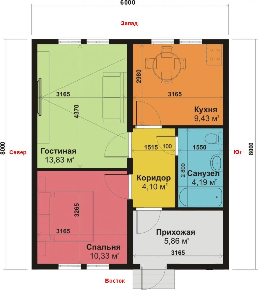
It is most convenient to depict the scheme of the house on paper, indicating not only the length, width and height of the building, but also the orientation with respect to the sides of the world, as well as the location, dimensions of the windows and doors (+)
The walls of the house under consideration consist of:
- brickwork with thickness B = 0.51 m, KT k = 0.64;
- mineral wool B = 0.05 m, k = 0.05;
- facing B = 0.09 m, k = 0.26.
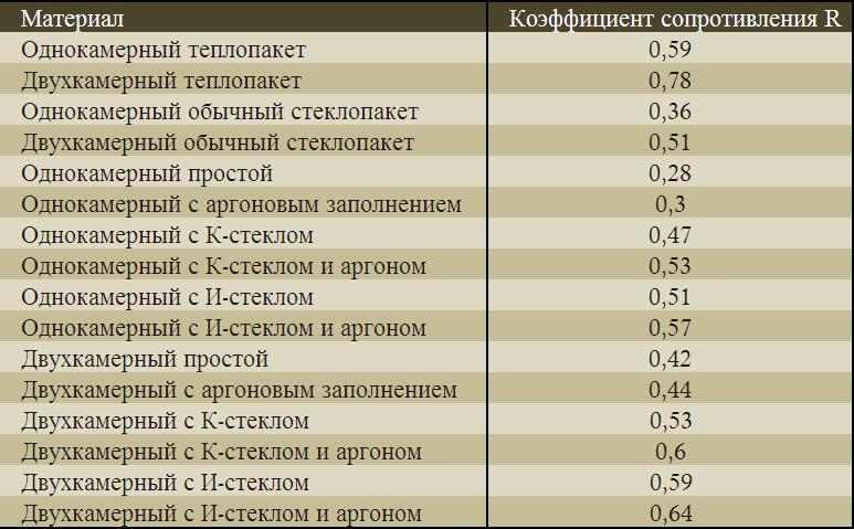
When determining k, it is better to use the tables presented on the manufacturer's website, or to find information in the technical passport of the product.
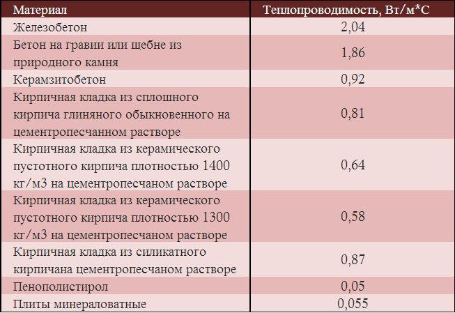
Knowing the thermal conductivity, you can choose the most effective materials from the point of view of thermal insulation. Proceeding from the above table, it is most expedient to use mineral wool plates and expanded polystyrene in construction
The floor covering consists of the following layers:
- OSB-plates B = 0.1 m, k = 0.13;
- min. B = 0.05 m, k = 0.047;
- cement screed B = 0.05 m, k = 0.58;
- foam polystyrene B = 0.06 m, k = 0.043.
In the house there is no basement, and the floor has the same structure throughout the whole area.
The ceiling consists of layers:
- sheets of plasterboard B = 0.025 m, k = 0.21;
- insulation B = 0.05 m, k = 0.14;
- roofing overlap B = 0.05 m, k = 0.043.
There are no exits to the attic.
In the house there are only 6 two-chamber windows with I-glass and argon. From the technical passport for the products it is known that R = 0.7. The windows have dimensions of 1.1x1.4 m.
Doors have the dimensions of 1x2.2 m, the indicator R = 0.36.
Calculating the heat loss of the wall
The walls throughout the area are made up of three layers. First, we calculate their total thermal resistance, using the formula:
and expression
Given the baseline information, we get:
Having learned R, it is possible to start calculating TP of the northern, southern, eastern and western walls.
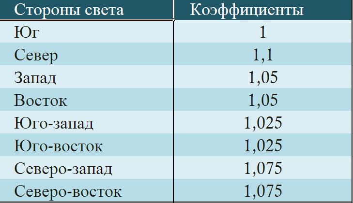
Additional coefficients take into account the peculiarities of the location of the walls with respect to the sides of the world. Usually in the northern part during the cold weather a "wind rose" is formed, resulting in TP from this side will be higher than from other
Calculate the area of the north wall
Then, substituting in formula
and taking into account that l = 1.1, we obtain:
Area of the southern wall. In the wall there are no built-in windows or doors, therefore, taking into account the coefficient l = 1, we get the following TP:
For the western and eastern walls, the coefficient l = 1.05. Therefore, you can find the total area of these walls, that is:
The walls have 6 windows and one door. Calculate the total area of windows and S doors:
Define S walls without taking into account S windows and doors:
We calculate the common TP of the eastern and western walls:
Having received the results, we will calculate the amount of heat leaving through the walls:
Total common TP walls are 6 kW.
Calculation of TP of windows and doors
The windows are located on the eastern and western walls, so when calculating the coefficient l = 1.05. It is known that the structure of all structures is the same and R = 0.7. Using the area values given above, we get:
Knowing that for doors R = 0.36, and S = 2.2, we define their TP:
As a result, 340 W of heat passes through the windows, and 42 W through the doors.
Definition of TP floor and ceiling
Obviously, the area of the ceiling and floor will be the same, and is calculated as follows:
Calculate the total thermal resistance of the floor, taking into account its structure.
Knowing that the soil temperature t nar = + 5 and taking into account the coefficient l = 1, calculate the floor Q:
Rounded, we get that the heat loss of the floor is about 3 kW.
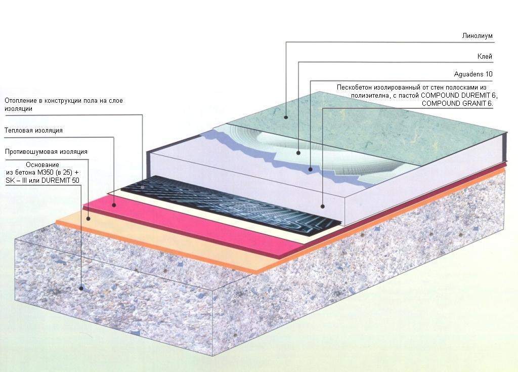
In the calculations of TP, it is necessary to take into account the layers influencing the thermal insulation, for example, concrete, boards, brickwork, heaters, etc. (+)
We define R ptl.
Having determined the thermal resistance of the ceiling, we find it Q:
Hence it follows that through the ceiling and the floor takes almost 6 kW.
Calculation of ventilation TP
In the room ventilation is organized, calculated by the formula:
Based on the technical characteristics, the specific heat exchange is 3 cubic meters per hour, that is:
To calculate the density, we use the formula:
The estimated temperature in the room is +21 degrees.
TP ventilation is not calculated if the system is equipped with an air heating unit
Substituting the known values, we get:
We substitute in the above formula the obtained figures:
Given the TP for ventilation, the total Q building will be:
Translated into kW, we get a total heat loss of 16 kW.
Peculiarities of calculation
After finding the indicator, the TP goes to hydraulic calculation (hereinafter - GR), on the basis of which information on:
- the optimal diameter of the pipes, which, when pressure drops, will be able to pass a specified amount of coolant;
- coolant flow in a certain area;
- water velocity;
- the value of the resistivity.
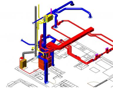
Before starting calculations, to simplify the calculations, a spatial scheme of the system is shown, on which all its elements are arranged in parallel to each other.
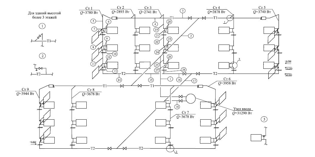
The diagram shows the heating system with an upper wiring, the coolant movement is a dead-end (+)
Let's consider the basic stages of calculations of water heating.
GR of the main circulating ring
The calculation procedure for GR is based on the assumption that in all risers and branches the temperature drops are the same.
The calculation algorithm is as follows:
- In the diagram shown, taking into account heat loss, apply thermal loads acting on the heating devices, risers.
- Based on the scheme, select the main circulation ring (hereinafter - FCC). The peculiarity of this ring is that in it the circulating pressure per unit length of the ring assumes the smallest value.
- The fcc is divided into sections having a constant heat consumption. For each section indicate the number, heat load, diameter and length.
In a vertical system of the single-tube type, a ring is taken as the FCC, through which the most loaded riser passes with a dead-end or by-pass water flow along the mains.
In vertical systems of a two-tube type, the FCC passes through the lower heating device, which has the maximum load at dead-end or passing movement of water
AT horizontal system one-tube type fcc should have the least circulating pressure and unit length of the ring. For systems with natural circulation the situation is similar.
With GR risers vertical system single-tube type flow, flow-regulated risers, which have unified nodes in their composition, are considered as a single contour. For risers with closing sections, separation is made, taking into account the distribution of water in the pipeline of each instrument cluster.
The water flow in a given area is calculated by the formula:
In the expression, alphabetic characters I take the following values:
- additional tabular coefficients, taking into account heat transfer in the room;
c - heat capacity of water, equal to 4.187;
- water temperature in the supply line;
- water temperature in the return line.
Determining the diameter and amount of water, you need to know the speed of its movement and the value of resistivity R. All calculations are most convenient to implement with the help of special programs.
GR of the secondary circulation ring
After the GR of the main ring, the pressure in the small circulation ring formed through its closest risers is determined, taking into account that the pressure loss can differ by not more than 15% in a dead-end scheme and no more than 5% at a passing one.
If it is not possible to reconcile the pressure loss, install a throttle washer, the diameter of which is calculated using software methods.
Calculation of radiator batteries
Let's return to the plan of the house placed above. By calculations it was revealed that 16 kW of energy would be required to maintain the heat balance. In the house under consideration there are 6 rooms of different purposes - a living room, a bathroom, a kitchen, a bedroom, a corridor, a hallway.
Based on the size of the structure, you can calculate the volume V:
- bathroom - 4.19 * 2.5 = 10.47;
- living room - 13.83 * 2.5 = 34.58;
- kitchen - 9.43 * 2.5 = 23.58;
- bedroom - 10.33 * 2.5 = 25.83;
- corridor - 4.10 * 2.5 = 10.25;
- the hallway is 5.8 * 2.5 = 14.5.
In calculations, it is also necessary to take into account the premises in which there are no heating batteries, for example, a corridor.
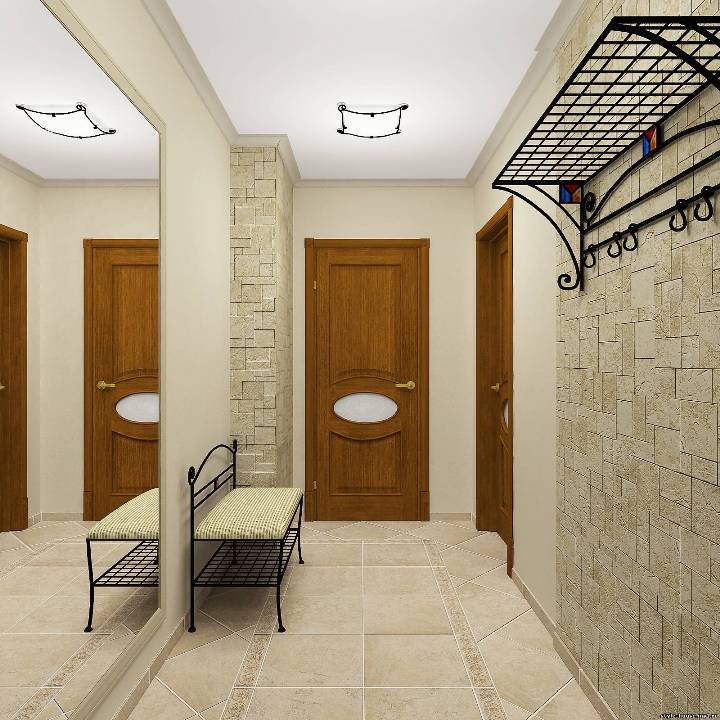
The corridor is heated by a passive method, heat will flow into it through the circulation of thermal air during the movement of people, through doorways, etc.
Determine the necessary amount of heat for each room, multiplying the room volume by the exponent P. We obtain the required power:
- for a bathroom: 10.47 * 133 = 1392 W;
- for the living room: 34.58 * 133 = 4599 W;
- for the kitchen: 23.58 * 133 = 3136 W;
- for the bedroom: 25.83 * 133 = 3435 W;
- for the corridor: 10.25 * 133 = 1363 W;
- for the hall: 14.5 * 133 = 1889 Tues.
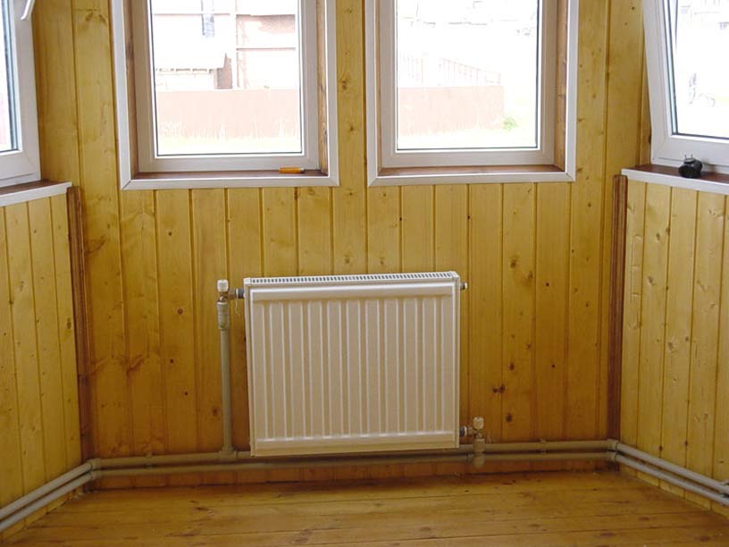
Let's start calculating radiator batteries. We will use aluminum radiators, whose height is 60 cm, the power at a temperature of 70 is equal to 150 W. Let's calculate the necessary number of radiator batteries.
- bathroom: 1392: 150 = 10
- living Room: 4599: 150 = 31
- kitchen: 3136: 150 = 21
- bedroom: 3435: 150 = 23
- entrance hall: 1889: 150 = 13
A total of 98 radiator batteries
Video example of calculating SVO
In the video, you can see an example of calculating water heating, which is implemented by means of the Valtec program:
Hydraulic calculations are best done with the help of special programs that guarantee high accuracy of calculations, take into account all the nuances of the design.
Everyone wants his home to be comfortable and cozy. This largely depends on maintaining a comfortable temperature in the house. But often, especially in winter, when the heating is incorrectly calculated, we notice that the air temperature in the house is either low, or vice versa, too hot.
Is it possible for a person who does not have the skills to calculate the system of water heating independently, without resorting to the services of professionals? Let's try to solve this problem.
The amount of heat consumed directly depends on such factors as loss of heat through the ceiling, floors, walls, and also through window and door openings. To calculate the heating it is necessary to determine which type of heating boiler you decide to install in the house to maintain the heat and the cost of heating (from the resources used). The calculation of water heating also depends on the structure of the building and the building materials of which the house is made. When choosing a boiler, it is necessary to take into account the availability to one or another source of heat, it can be coal, electricity, gas, liquid fuel, wood, and also it is important to take into account the cost of purchasing fuel for the house, respectively, the less is the better.
Consider the types of boilers
1. Solid fuel boiler. If you expect to save, then get ready that the wood or coal will be heated and uneven. However, if you purchase a high-quality automatic boiler of foreign production, then this option can be considered as a priority.
2. Electric boiler. Due to the high cost of electricity, this type of boiler is not very popular. In addition, to use this boiler requires a well-established and permanent electrical network. Therefore, in areas with an unstable power grid or where there are frequent power outages to use an electric boiler is not rational.

3. Liquid fuel boilers. If for your region liquid fuel is the most economical, then, as an option, it is very suitable. But the drawback is that for ecology is not the best option.

4. Gas fired boilers. If your house is connected to natural gas, this option will be very good. Gas has the highest coefficient of efficiency. A gas boiler can be put in any room, even in the kitchen and at the same time its safety is very high.

The main parameters for calculating the capacity of water-heating boilers are the specific power of the boiler and the area of the house. If the total area of the building exceeds one hundred square meters, it is necessary to include in the calculation of water heating a circular pump that circulates water through the heating system.
Also in the calculation of water heating it is necessary to include the calculation of the number of radiators, the cost of the pipeline.
To calculate the number of batteries, it is necessary to calculate the heat transfer of one section of the radiator and divide by one hundred, so we know the number of square meters that the battery can heat.
When calculating the cost of water heating, it is necessary to take into account the pipeline, for the installation of which, respectively, pipes are purchased. The copper pipeline is considered the most reliable, it withstands high temperatures and high pressure, on this, it is safe even when mounted inside the walls. The disadvantage of a copper pipeline is its high cost. Steel pipes If they are not galvanized, they are used welding work. Polymer pipes They have good mechanical strength, are oxygen-proof, have a low weight, are easy to assemble.
Rating: 569
Everyone is looking for the most optimal heating and heating quality for their homes. The most striking example is in a private house. During the winter, this system for many years of practice managed to prove itself from the very best side. Heating, such as, e and, gone into history, everything in great demand enjoys water heating.
The simplicity of the mechanism is especially popular with water heating - water, heated to the desired temperature level, flows through pipes to radiators or batteries installed in residential premises, where it gives its heat, and then returns to the boiler. If necessary. In this, you can include other elements - to remove excess water generated by heating, it serves. Due to this, there is no oxygen in the system.
It is another additional mechanism of water heating. The pump serves to increase the speed of heating the temperature in the premises due to the faster movement of water along, while maintaining a continuous water cycle in the system. The thermostat, the airtracker, the pressure gauge, - the diligent master will include them in his heating system.

Arrangement of water heating
The boiler is the main element of the water heating system in a private or suburban house. The size of the boiler is calculated based on the size of the premises in the house - 1 kW per 10 square meters, which must be heated. It should be taken into account and such a moment - the height of the ceilings should not exceed 3 meters.
When calculating it is necessary to take into account both the size of the windows, the level of insulation of the house, additional heat consumers, the volume of premises.
Approximate calculations show that the boiler output is equal to:
- Up to 25 kW - the size of the room from 60 to 200 square meters. m;
- 25 - 35 kW - dimensions of the room from 200 to 300 square meters;
- 36 - 60 kW - dimensions of the room from 300 to 600 square meters. m;
- up to 100 kW - room dimensions from 600 to 1200 square meters. m.
For mounting the water heating system at the dacha or in, it is sufficient to select an electric boiler with a capacity of 3 - 105 kW, with an area not exceeding 1000 sq. M. m. But the high cost of electricity, interruptions and differences in its supply, insufficient capacity - are disadvantages of electric boilers.
Should be vigilant and when. It is possible to use pipes from various metals, assessing the advantages and disadvantages of each. were the most in demand, but today they are used less and less. The main disadvantage of this type of pipe is its high susceptibility to corrosion processes.
The most popular steel and stainless steel. also gaining popularity. Durability, the ability to withstand high temperatures - these are the most significant characteristics of this type of pipe. The main obstacle is the price. Increasingly you can meet in the water heating with. This kind of pipe is made of metal-plastic or propylene, with the participation of aluminum. The main difference is strength, corrosion resistance, the sediment inside such pipes is practically not delayed. But a much higher coefficient of expansion with heating plays a negative role.

Necessary equipment
Traditionally, there are two schemes of water heating - one-circuit and two-circuit. If the house is up to 100 sq.m. - a more simple scheme of water heating, one-circuit, is an example of such a system of water heating is. This system includes atmospheric exhaust, single-pipe wiring made of polymer or steel pipes and radiators (cast iron, aluminum or steel pipes).
Such heating can be improved by two-pipe wiring, circulation pump, valves with thermoregulation for radiators.

Single-circuit system
The system of water heating is suitable for heating domestic water, it is enough to reconsider the installation of a boiler or gas column. Or you can mount it, designed for both heating and water heating. This dual-circuit water heating system is a very convenient option for a private home.
This system of water heating in a private house will satisfy the needs of a family of four. But you should take into account the level of water hardness - the most optimal tap water, rigid, from the well, will not work. Alternatively, two single-loop systems can be installed: one of them will be responsible for the heating of the premises, and the other for the heating of the water. In summer, such a system will allow only to heat water, which will save up to 25% of the boiler's capacity.

Two-circuit system
When installing water heating in or private, you should apply three options for pipeline layout - single-pipe, two-pipe and manifold.
A system in which heated the water is coming from the boiler in series to each of the batteries - is called single-tube. A very big drawback of such a system is the difficulty in controlling the wiring, since when access is blocked in one radiator, water access to all other radiators is blocked.
A system in which a pipe with a cold and hot water - is called two-tube. The big advantage of such a system is the convenience of heating regulation.
And, finally, collector or heating. The main principle of operation is that from the device that collects water (collector) two radiators are connected to each radiator - direct and feedback. It is thanks to this principle that it is possible to install a heating system with hidden wiring pipes. It is also possible to maintain the set temperature in each room and control it.

Traditional distribution of water heating pipes
When planning such a house, it is optimal to consider all options - and collector circuit, and two-pipe wiring.
The most practical and versatile option is the two-pipe system of the water heating system. In this scheme, two pipes are supplied to each device participating in the heating, one for supplying water, and the other for discharging it.
According to experts, it is optimal if an adjusting valve is supplied before each radiator.
But the collector at its installation in is an expensive pleasure. Also popular is water heating with such a system in these houses. The advantage in this case is obvious: the installation of the pipeline is hidden, apparently the interior does not suffer. It is possible to place pipes under the windowsills, floor, and even - under the ceiling. It is advisable to place the boiler on the ground floor, and expansion tank - Upstairs. The installation of a control valve on each radiator makes the system even more efficient. After all, depending on the needs of each member of the family, you can choose the most optimal mode of heating the room.

Heating scheme for a two-storied house
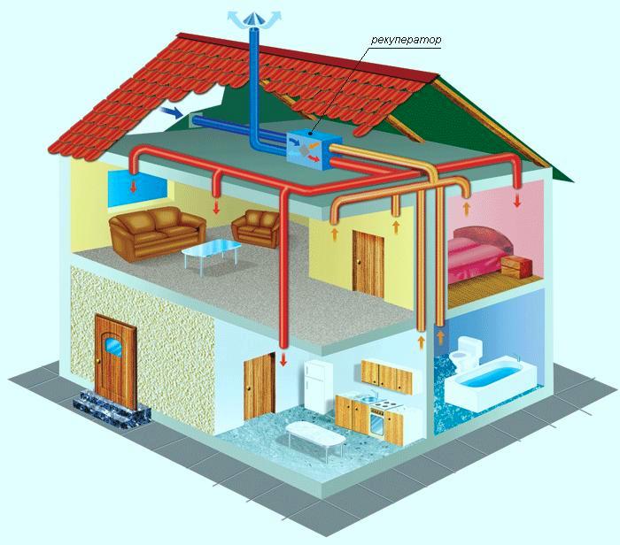
In addition to the above methods of heating the house there are other types of alternative water heating in a private house. To modern heating systems include the system "warm floor". At the heart of the same principle of water heating, but the system "warm floor" can be used as an addition to the main heating system. Its advantage lies in the larger area of heat transfer. The floor in the room becomes a big "radiator". Air after the installation of the system "warm floor" starts to warm up in the right direction - the bottom is warmer, at the top - it's cooler. Due to this, the operating mode of the coolant can be reduced to 55 degrees Celsius. Another advantage of the "warm floor" system - the thermal power can be set in the right range.
The disadvantages of the "warm floor" system include the complexity of installation, the impossibility of installing it with the already completed installation of a heating system in such a house - you will either deepen the floor or raise it.
This is another option for an alternative heating system. At its core plinth heating is something intermediate between the two systems - the radiator and the "warm floor". When installing this heating system, the equipment is placed around the perimeter of the room at the height of the skirting board. It is thanks to this installation of equipment that the walls and the floor are evenly heated. The air also warms evenly and in the right direction.

Water plinth filling
A big advantage of such a system of water heating is the arrangement of the interior without the installation of large radiators, but with the preservation of heat in the premises of a private or suburban house.
Video: calculation of water heating of a private house
In conclusion
Before installation, the heating system in a private or country house should carefully consider everything, consider all available options for heating systems, consult with a specialist in the field, which will help you navigate in all the diversity modern systems heating, pick up the most the best option. The main thing - that the house was warm in any weather!
Your contacts in this article are from 500 rubles per month. Other mutually beneficial options for cooperation are possible. Write to us on [email protected]
Pipelines in the heating system perform an important function of the distribution of the heat carrier by separate heating devices.
In water systems, the amount of heat brought by the heat carrier depends on its flow rate and the temperature drop when the water in the device is cooled. Usually, in the calculation, the temperature drop of the coolant is common for the system and tend to ensure that two-pipe systemsthis difference was maintained for all devices and for the system as a whole, in single-pipe systemsah - for all risers. With a known drop in the temperature of the coolant through the pipelines of the system, a certain flow of water must be connected to each heating device.
In engineering practice this problem is solved by the selection method.
Carry out a hydraulic calculation of the pipeline network of the heating system (taking into account the available circulating pressures) - this means choosing the diameters of individual sections so that the estimated costs of the coolant pass through them. The calculation is carried out by selection with the choice of diameters according to the available assortment of pipes, therefore it is always connected with some error. For different systems and some of their elements are allowed certain discrepancies, which must be sustained in the calculation.
Loss of pressure in pipeline sections. The movement of water in the pipelines occurs from sections with high pressure to sections with a lower pressure. The pressure is lost to overcome frictional resistance along the length of the pipes and local resistances. In water heating systems, the share of frictional losses and in local resistances is approximately the same, so they must be equally taken into account in hydraulic calculations. In the heating system, water circulates in a closed loop. According to the Bernoulli equation, the pressure difference Δp During the arbitrary contour of the pipeline system should be equal to the sum of hydraulic friction losses Δp tr and in local resistances Δp ms . :
Δp = Δp mp + Δp ms (5.18)
Given the complexity of calculating the pressure loss due to friction by formulas, tables or nomograms are usually used. Loss of pressure on friction Δp mp is determined from expression
Δp mp = Rl,(5.27)
where R -specific losses of pressure on friction (referred to 1 m of pipe length).
Value Ris obvious from (5.19). Table for determining the value of the specific frictional pressure loss R,Pa / m, depending on speed υ, m / s, or flow rate G, kg / h, water flowing through pipes of different diameters d,mm, is given in approx. 7.
Loss of pressure in local resistances Δp ms are usually denoted by a letter Z. The amount Z can be determined by formula
Z = Σξ(5.28)
where ξ - coefficient of pressure loss in local resistance, or abbreviated local resistance coefficient.
Coefficient ξ characterizes the hydraulic characteristics of various local resistances
In Appendix 8, the values of local resistance coefficients for various elements of heating systems are given. The numerical values of the coefficients ξ especially for tees and crosses, depend on the absolute and relative values of flow rates of flowing pipes and pipe diameters, therefore, the data given in the appendix are approximate. They can be reliably used to calculate two-pipe systems and main sections of single-pipe systems.
Part of the pipeline system, within which the flow rate of the coolant, as well as the diameter of the pipe remain unchanged, is called site. On the site there may be several local resistances. Are common hydraulic losses pressures Δp i, within the settlement area i are equal:
Δp i = (Rl + Z) i. (5.29)
Circulating in the heating system, the streams consistently pass through a number of sections. Loss of pressure in series connected sections Δp equal to the sum of pressure losses in individual sections:
Δp =  (5.30)
Pipelines of the heating system form a series of interconnected parallel rings; at separate points of the system the streams diverge, and in others converge, forming, as it were, the semirings of one closed contour. The pressure drops, under the influence of which the water moves along each of the semirings between the common points of fission and fusion, will be the same. So it will be under isothermal conditions.
We can formulate a general rule: the pressure losses on the half rings between the common points, taking into account the additional gravitational pressures, are equal to each other.
In Fig. 5.6 two schemes of the heating system are shown: the dead-end and with the associated movement of water in the supply and return pipelines. Schemes are drawn in a simplified form, they show only the mains and risers without heating appliances, armatures, etc. On the example of these schemes and on the basis of the formulated general rule it is convenient to write the equations for linking individual piping semirings in the system.
In a dead-end scheme in the circulation ring of risers I and Vfrictional losses and local resistance at the site agshould be equal to the sum of losses on sites ab, bwand in. In the scheme with a passing motion in the circulation ring of risers I and V the sum of friction losses and local resistances at sites agand gWshould be equal to the sum of losses in the plots aband bv.However, since in both schemes the water is on the way from the boiler to the riser Vcools more than the way from the boiler to the riser I, and, consequently, the corresponding gravitational pressures Δp e for risers I and Vdifferent, consumed pressure on the pipelines in question are written in the following form:
for a dead-end scheme
Σ (Rl + Z) ar = Σ (Rl + Z) abgg - (Δp e abbg - Δp e ar)(5.31)
for a scheme with a passing motion
Σ (Rl + Z) aug = Σ (Rl + Z) abb - (Δp e abv - Δp e arv)(5.32)
The gravitational pressure at each of the parallel branches will be determined by the general formula (5.5). In this case, it is necessary that for each considered pipeline contour the plane of reference of the heights of the individual heating or cooling points on the half rings is common. It is usually convenient to count from a plane passing through the points of division or confluence of the flows of circulation loops.
Method of hydraulic calculation of pipelines of water heating systems.
The method of hydraulic calculation of heating systems is based on the regularities of circulation of the coolant in the pipeline system and determines the sequence of this calculation. Usually the task is to determine the diameters in individual sections at given flow rates and pressures. Calculation begins with the determination of the available circulating pressure. The amount Δp (5.15) for systems with natural circulation or by formula (5.16) for pumping systems and systems connected to a heat network.
When calculating for the main (most unfavorably disassembled hydraulically) circulating ring, one accepts for which the available circulating pressure per 1 m of the length of the pipeline proves to be the smallest.
In dead-end schemes of two-pipe systems (see Fig. 5.6, a) the main is usually a circulating ring passing through the lower riser instrument.
In the dead-end schemes of single-tube systems, the main thing is the ring passing through the far riser.
In schemes with a co-moving motion (see Fig. 5.6, b) the length of the rings through the lower-floor appliances for all the risers is approximately the same. In this case, the pressure drop in the system is not limited in advance, but the diameters of the pipelines are selected from the condition of the maximum permissible velocities of the coolant motion and the possible coordination of the hydraulic pressure losses along separate parallel semirings of the systems
In this case, it is convenient to take as the main one a ring passing through the lower device (in a two-tube system) of one of the middle most loaded risers. It is this riser in the schemes with the associated motion (including single-tube systems) that proves to be the most disadvantageous in terms of hydraulics.
The task of hydraulic calculation of the main circulating ring is to select the diameters of its individual sections in such a way that the total pressure losses along the ring Σ (Rl + Z) g.v. were 5-10% less than the design pressure Δp r.s., i.e.
Σ (Rl + Z) g.v. = (0.9 ... 0.95) Δp (5.33)
Some reserve of pressure is necessary in the case of unaccounted hydraulic resistances.
The main circulation ring calculated in this way is adopted in the further calculation as a reference for the hydraulic linking of all other rings of the system. All the circulating rings of the system are, as it were, tied hydraulically to the main ring. For each circulation ring, there are points common to the main ring where fission or fusion occurs. One of the semirings between these common points is always composed of the already calculated sections of the main ring. The task is to select the diameters of the sections of the second half-circle in such a way that the hydraulic losses in them are (taking into account the additional gravitational pressures) equal to the already calculated pressure loss between the common points on the sections of the main circulation ring [ formula (5.31) or (5.32)].
At the same time, the closer the values of those and other losses, the better. It is not always possible to accurately link pressure losses in semirings, but it is necessary to withstand a certain magnitude of the discrepancy between them. In water heating systems SNiP allow a discrepancy of up to ± 15%.
The discrepancy between the pressure losses in the semirings passing through devices of different floors of risers of two-pipe systems is not limited by the norms, since it must be eliminated by the installation adjustment of the system using double-adjustment valves.
Calculation of the water heating system of a private house.
Is it possible to design, calculate and install heating systems at home, without resorting to the services of professionals for this? If you are serious, and are ready to activate all your reserves of extreme attention, then no problem! I will teach you how to produce necessary calculations volume, using for this the simplest formulas that do not require a program and will not cause you any difficulties.
Calculation of the heating boiler, depending on its type
It is very important to determine in advance which type of boiler will be installed in your home. Determine this issue, I recommend on the basis of what source of heat is most available for your region. It can be gas, solid coal, liquid fuel, electricity. In general, what kinds of fuel for heating a residential house will cost you a smaller amount, and prefer these.
1. Electric boilers. In our country this type of heating boilers is not very popular, which is explained by the cost of electricity. In addition, an electric boiler requires a well-adjusted electrical network, as a result of which for many modern Russian settlements electric boiler is not recommended.
2. Solid fuel boilers. Everything will depend on how much you are willing to be generous. If you want to save, be prepared for a constant pouring of coal and uneven heating of the coolant. Well, if you are going to purchase a really high-quality automatic boiler of foreign production, then by calculating the radiators of heating, you can consider this option as a priority.
3. Gas boilers. Gas has the highest coefficient of efficiency, and the safety of gas boilers at the highest level. And if your vacation home connected to gas pipe, I strongly recommend that you take a closer look at this variant with the greatest attention, since it is possible to put such a boiler even in the kitchen.
4. Liquid fuel boilers. For the environment this is the most unattractive option, but if liquid fuel for your region is the most economical, this parameter can be considered insignificant.
Calculation of the heating system power
To make the necessary calculations of the heating system, I suggest using a fairly simple formula or technique. It is necessary to multiply the area of the room by the specific climatic power and divide the result by 10.
1. The area of the room. It may seem that this parameter is the easiest to compute. In most cases, people take the area of all living rooms, where it is desirable to establish a comfortable temperature. And this is a big mistake. I remind you that willy-nilly, all rooms will be heated, without exception, including corridors, if you do not seal them. Therefore, when calculating the capacity of the heating boiler, take the entire area of the house as a whole.
2. Specific climatic power. This indicator is based on your region of residence. For the central regions of our country the coefficient is at the level of 1.2-1.5 kW, for the southern regions - 0.7-0.9 kW, and in the northern regions it increases to 1.5-2.0 kW. I do not need additional explanations here.
I give an example that is based on real practice. With a house area of 100 squares located in the central region of Russia, the capacity of the used heating boiler should be 100х1.2 / 10 = 12 kilowatts or 15 kilowatts if you think that your central area is rather cold.
Calculation of the number of radiator sections
When you figure out what type of boiler you will use, and what will be its power, you can start calculating the number of sections in the batteries used. Here I also suggest using a fairly simple formula. It is necessary to multiply the heated area by 100 and divide by the capacity of the battery section.
1. The area of the room. Since the radiators are designed exclusively for heating one room, the area of the whole house we do not need. Familiar specialists gave me a very valuable recommendation. The standard formula can only be used if adjacent rooms are also heated by the above formula. If for some reason, you left the next "storage room" without heating, then the calculation of the number of radiators will have to be carried out taking into account the fact that some heat can leave the room in the "cold" direction.
2. The figure 100, which appears in my formula, is not taken from the ceiling. The fact is that the corresponding SNiP prescribes using 100 watts of power per square meter of a dwelling, which is quite enough to establish a comfortable temperature.
3. Regarding the power of the radiator section, it is individual and depends on the material from which the battery is made. If you can not accurately determine this figure, I recommend to base calculations on 180-200 watts, which corresponds to the average power of the section of modern radiators.
So, we calculate the heating batteries by example. With a room size of 20 squares and a section capacity of 180 watts, the number of sections is calculated as follows. Multiply 20 by 100 and divide by 180. We get about 11 sections of the heating battery. In addition, you can multiply this value by 1.2, if the room is located on the corner or at the end of the building.
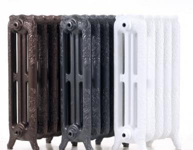
Radiator materials for heating
It remains to determine the material from which radiators will be made, for which water will run in your heating system in the cottage. Tubular steel batteries, I recommend immediately discard. Perhaps they are cheap, but firstly, they are guaranteed only 1 year, and secondly they have low power sections at 85 watts. Cast iron radiators can boast greater reliability, but the capacity of the sections is only slightly higher than that of steel - 110 W. I suggest not to spare money and buy anodized radiators with good corrosion protection, a 30-year warranty and a power of 215 watts.
How to make a heating system installation by yourself: