Calculation of hydraulic losses in the pipeline example. We make the hydraulic calculation of the heating system with the help of programs, ready-made Excel forms and independently
What is the hydraulic calculation of the heating system? What quantities need to be counted? Finally, the main thing: how to calculate them, not having accurate values of the hydraulic resistance of all areas, heating devices and elements stop valves? Let's understand.
What we expect
For any heating system, the most important parameter is its heat output.
It is determined by:
- The temperature of the coolant.
- Thermal capacity of heating appliances.
Note: in the documentation, the last parameter is indicated for a fixed temperature delta between the coolant temperature and air in a heated room of 70 ° C.
Reducing the delta of temperatures by half will result in a twofold decrease in thermal power.
Methods for calculating the thermal power, we still leave behind the scenes: they are devoted enough thematic materials.
However, in order to ensure the transfer of heat from the route or boiler to the radiators, two more parameters are important:
- The internal section of the pipeline, tied to its diameter.
- The flow rate in this pipeline.
In an autonomous heating system with forced circulation it is important to know a couple more values:
- Hydraulic resistance of the circuit. Calculation of the hydraulic resistance of the heating system will determine the requirements for the pressure created by the circulation pump.
- The flow of the heat carrier through the circuit, determined by the capacity at the corresponding head.
Problems
As they say in Odessa, "they are."
In order to calculate the total hydraulic resistance of the circuit, it is necessary to take into account:
- Resistance of straight pipe sections. It is determined by their material, internal diameter, flow velocity and degree of wall roughness.
- Resistance of each rotation and diameter transition.
- Resistance of each element of the stop valve.
- Resistance of all heaters.
- Resistance of the boiler heat exchanger.
Collecting all the necessary data will clearly become a problem even in the simplest scheme.
What to do?
Formulas
Fortunately, for offline heating system Hydraulic calculation of heating can be performed with acceptable accuracy and without deepening into the jungle.
Flow rate
On the lower side, it is limited by the growth of the temperature difference between the feed and the return flow, and at the same time the increased probability of ejection. A fast flow will force air from the jumpers to the automatic air vent; A slow one can not cope with this task.
On the other hand, too fast flow will inevitably generate hydraulic noise. Elements of stop valves and rotations of bottling will become a source of irritating hum.

For heating, the range of acceptable flow rate is taken from 0.6 to 1.5 m / s; while the calculation of other parameters is usually performed for a value of 1 m / s.
Diameter
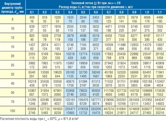
It is easiest to select it with the known thermal power from the table.
| Inside diameter of pipe, mm | Heat flow, W at Dt = 20С | ||
| Speed 0,6 m / s | Speed 0,8 m / s | Speed 1 m / s | |
| 8 | 2453 | 3270 | 4088 |
| 10 | 3832 | 5109 | 6387 |
| 12 | 5518 | 7358 | 9197 |
| 15 | 8622 | 11496 | 14370 |
| 20 | 15328 | 20438 | 25547 |
| 25 | 23950 | 31934 | 39917 |
| 32 | 39240 | 52320 | 65401 |
| 40 | 61313 | 81751 | 102188 |
| 50 | 95802 | 127735 | 168669 |
Head
In a simplified version, it is calculated by the formula H = (R * I * Z) / 10000.
In it:
- H - the desired value of the pressure in meters.
- I - loss of pressure in the pipe, Pa / m. For a straight pipe section of the design diameter, it assumes a value in the range of 100-150.
- Z - additional compensation factor, which depends on the presence of additional equipment in the circuit.
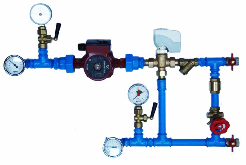
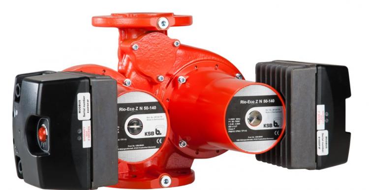
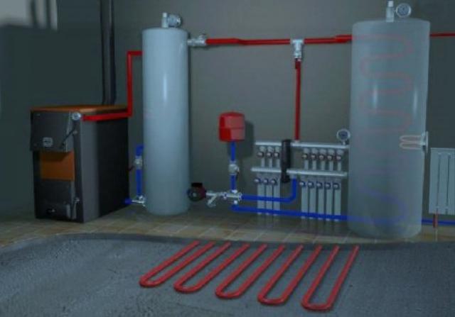
In the photo there is a mixing unit for heating.
If there are several elements in the system, the corresponding coefficients are multiplied. So, for a system with ball valves, and a thermostat controlling the flowability of filling, Z = 1.3 * 1.7 = 2.21.
Performance
The manual for calculating the pump's own performance is also not difficult.
Performance is calculated by the formula G = Q / (1,163 * Dt), in which:
- G - productivity in m3 / hour.
- Q is the thermal power of the circuit in kilowatts.
- Dt is the temperature difference between the supply and return pipelines.
Example
Let's give an example of the hydraulic calculation of a heating system for the following conditions:
- The delta temperature between the supply and return piping is equal to the standard 20 degrees.
- Thermal power boiler - 16 kW.
- The total length of the single-tube Leningrad tower is 50 meters. The heating devices are connected in parallel to the filling. Thermostats that break the filling, and there are no secondary circuits with mixers.
So, let's get started.
The minimum internal diameter according to the above table is 20 millimeters with a flow velocity of at least 0.8 m / s.
Useful: modern circulating pumps often have stepped or, more conveniently, a smooth adjustment of performance.
In the latter case, the price of the device is slightly higher.
The optimal head for our case will be (50 * 150 + 1.3) / 10000 = 0.975 m. Actually, in most cases the parameter does not need a calculation. Differential heating system apartment building, providing it with circulation - only 2 meters; this is the minimum value of the pressure of the absolute majority of pumps with a wet rotor.
The productivity is calculated as G = 16 / (1,163 * 20) = 0,69 m3 / hour.
Conclusion
We hope that the above calculations will help the reader to calculate the parameters of his own heating system without climbing into the jungle of complex formulas and reference data. As always, the attached video will offer additional information. Good luck!
The availability of a productive heat generator, quality pipes and modern radiators does not mean that heating will be effective. If the system is improperly designed, then situations are possible when a fully working boiler can not provide a comfortable temperature in all rooms. Either there is enough heat, but the energy costs are prohibitive. In order not to make irreparable mistakes, it is necessary to develop a project, an important part of which is hydraulic calculation heating systems. Perhaps the most difficult part.
Why calculate the hydraulics of the heating system
The essence of the problem
Modern heating installations are dynamic systems that, during operation, operate in different operating modes. The heating medium of water heating circulates under pressure, but this value is not constant. Losses occur on different sites because of constructive features systems (friction against the walls of pipes, resistance at fittings, etc.). We also manipulate the pressure ourselves, when we balance the distribution of heat through the rooms with the help of fittings. Manually or through system automation, the user controls the power of the heating device, changes the level of heating of the coolant. Again, the head of the network jumps, because the higher the temperature, the higher the pressure, and vice versa.
The pressure drop in a particular area leads to a decrease in its thermal performance. Quality heating should work in all conditions stably and economically, but for this it is necessary that to each radiator there should be exactly as much coolant as necessary for replenishing heat losses in the room and maintaining the set temperature.
Decision
One of the main tasks of the developer is to reduce possible head loss, which allows improving the regulation of individual sections and the system as a whole. There is a special term for "increasing the authority of the valve." It means that the local resistance, which the valve or valve has to the flow in the regulated branch, more favorably corresponds to the working pressure in the section. The more the volume of the coolant the concrete element controls, the more valuable it is.
Informative table as a result of hydraulic calculation
Also it is necessary to make a hydraulic linkage of the circulating rings. Competent use of balancing valves, valves, pressure regulators allows to avoid overheating of the rooms close to the boiler and the lack of heat in the remote (excess steam in the room - this is an over-expenditure of heat at the level of 5-10 percent). Restricting the flow in one branch, we increase it for others - we redistribute the coolant.
So, hydraulic calculation of heating helps the design engineer to solve the following tasks:
- calculate the throughput of pipelines and the drop in head on the main and secondary contours;
- select the cross-section of the pipes, if the flow rate of the coolant and the pressure in the system are already set;
- calculate the optimal ways of balancing the branches of the system;
- identify required power circulation pump.
Stages of carrying out hydraulic calculation of heating
Collection and systematization of source data
Before starting the calculations, the developer studies the thermal and technical characteristics of the object and prepares a suitable version of the heating system on the basis of TK. Perform the following activities:
- The heat calculation is performed, as a result of which information on the necessary amount of heat for each room is obtained.
- Choose a heat generator and heaters.
- Decide on the methods of piping and the features of balancing the system.
- Choose the type of pipe and the specification of the control valve.
- Make up the axonometric wiring diagrams and detailed plans of the premises with indication of the basic initial data (coolant flow, battery power, arrangement of equipment, etc.). Nodal points, the main contour and individual sections are marked, the length of the rings is denoted.
Selecting a method
There are several ways to calculate the hydraulics of the heating system (as a rule, they are all performed using special software):
- addition of conductivity and resistance;
- by specific pressure loss;
- along the length of pipelines;
- comparison of dynamic pressures;
- by volume of the transported coolant.
The specific method is used depending on whether the temperature differences in the system are dynamic or stable. Also, the heating configuration is taken into account: some calculation methods are suitable only for single-pipe wiring schemes, others are universal. Most often, the hydraulic calculation of the heating system pipelines is used for pressure losses.
Pipe cross-section calculation
Choosing the optimal pipe size is one of the most effective methods of controlling the performance of a heating system. Thus, the use of pipes with an overstated section entails:
- growth of capital expenditures;
- decrease in working pressure;
- a critical decrease in the rate of transfer of the coolant with a high probability of ejection;
- the appearance of a significant thermal inertia of heating.
Reducing the diameter of pipelines can reduce both capital and operating costs, but leads to an increase in the flow velocity. At rates from 0.6 m / s in the system there are noises, therefore optimal for residential premises is the speed of transportation of the coolant in the range of 0.3-0.7 meters per second.
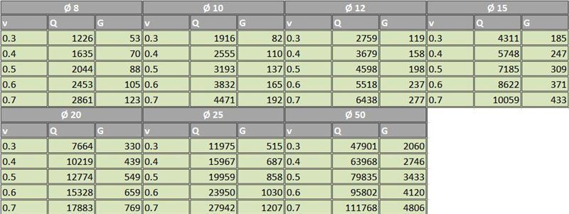
To calculate the appropriate internal diameter of pipelines, the following data is used:
- The difference between the flow and return temperatures (for two-pipe circuits it is usually assumed to be 20 degrees).
- The coolant flow rate is indicated in the tables with the letter "G". In real calculations and in examples of hydraulic calculation of heating systems, this quantity, as a rule, is already preset.
- The rate of movement of water / antifreeze - is indicated by the letter "v"
- Density of coolant.
- The volume of heat flow is indicated by the letter "Q".
- Features of the site (length, number of sections in radiators, etc.).
Determination of pressure losses in the system and its individual sections
At each site, the overall pressure drop is due to two main factors:
- Resistance to friction, which arises from the roughness and roughness of the inner walls of the pipes.
- Local resistance, which has on the transfer of working media connecting fittings, shut-off valves, turns and branches, narrowing / expanding pipelines. Also, the braking effect is created by heat exchangers of heating appliances and heat generators.
The level of pressure loss in the ring due to frictional resistance depends on:
- flow rate;
- coefficient of roughness of pipeline material;
- the length of the branch;
- diameter and shape of the internal section of the pipes;
- viscosity and density of the coolant.
The nature of local resistance is affected by:
- rate of fluid transfer;
- coefficients of local resistance (data for various nodes and devices are tabulated).
Accurate calculations are made according to generally available formulas, the results on resistances in individual sections are summed up, and the engineer is able to calculate the required productivity pumping equipment.

Such schemes are generated by programs for hydraulic calculations
Development of coordination of circulation rings
The final stage of hydraulic calculation of the heating system. Analyzing the initial data obtained at preliminary stages (resistance, necessary heat loads, characteristics of the valve), the designer should equalize the pressure losses in the network. That is, ideally, the pressure loss in all rings of the system should be the same. To balance the head and redistribute the flow of coolant, manual valves or automatic valves are used, which are responsible for individual branches or installed on each heater. It is based on the results of hydraulic calculation, the preliminary adjustment of the control valves is performed.
Video: practical lesson of hydraulic calculation of heating system
For the efficient operation of the heating system, it is necessary to fulfill several conditions - to correctly select the components and make the calculation. From the correct calculation of the parameters of the system depends on its efficiency and uniform heat distribution. How to make a hydraulic calculation of heating systems - examples, the programs will help to carry out these calculations.
Purpose of hydraulic calculation of heating
When any heat supply system is operating, a hydraulic resistance inevitably arises when the coolant moves. To account for this parameter, a hydraulic calculation is necessary two-pipe system heating. Its essence lies in the correct choice of system components taking into account their performance.
In fact, the hydraulic calculation of water heating systems is a complex procedure, during which all subtleties and nuances are taken into account. At the first stage it is necessary to determine the required heating power, choose optimal scheme distribution of pipelines, as well as thermal operation. On the basis of these data, a hydraulic calculation of the heating system in Excel or a specialized program is done. The result of the calculations should be the following parameters of water heat supply:
- Optimal diameter of the pipeline. Based on this, one can know their throughput, heat losses. Taking into account the choice of the material of manufacture, the resistance of the water to the inner surface of the main line will be known;
- Loss of pressure and pressure in certain parts of the system. An example of a hydraulic calculation of a heating system will allow you to think in advance of the mechanisms for their compensation;
- Water flow rate;
- Required capacity of pumping equipment. Actual for closed systems with forced circulation.
At first glance, the hydraulic resistance of the heating system is difficult. However, it is enough to delve into the essence of calculations and then you can do them yourself.
For the heat supply of a small house or apartment, it is also recommended to perform a calculation of the hydraulic resistance of the heating system.
Procedure for calculating hydraulic parameters of heating
At the first stage of calculating the parameters of the heating system, preliminary scheme, which indicates the location of all components. This determines the total length of the mains, calculates the number of radiators, the volume of water, as well as the characteristics of the heating appliances.
How to make a hydraulic calculation of heating, without the experience of such calculations? It should be remembered that for autonomous heat supply it is important to choose the correct diameter of the pipes. It is from the implementation of this stage that we must begin the calculations.
It is best to make a heating scheme on an already prepared house plan. This will allow you to correctly calculate the consumption of material and determine its quantity for the arrangement of the system.
Determination of the optimal diameter of pipes

The simplest hydraulic calculation of a heating system involves only calculating the cross-section of pipelines. Often, when designing small systems, they do without it. For this, the following parameters of pipe diameters are taken, depending on the type of heat supply:
- Open circuit with gravitational circulation. Pipes from 30 to 40 mm in diameter. Such a larger cross-section is necessary to reduce losses due to water friction against the internal surface of the mains;
- Closed system with forced circulation. Cross-section of pipelines varies from 8 to 24 mm. The smaller it is, the greater the pressure in the system and, correspondingly, the total volume of the coolant will decrease. But at the same time, hydraulic losses will increase.
If there is a specialized program for hydraulic calculation of the heating system - it is enough to fill in the data on technical characteristics boiler and transfer heating circuit. The software kit will determine the optimum pipe diameter.
The received data can be checked independently. The procedure for performing hydraulic calculation of a two-pipe heating system manually when calculating the diameter of pipelines consists in calculating the following parameters:
- V - speed of water movement. It should be in the range from 0.3 to 0.6 m / s. Determine the performance of pumping equipment;
- Q - heat flow. This ratio of the amount of heat passing in a certain time interval is 1 second;
- G - water flow. Measured in kg / hour. Directly depends on the diameter of the pipeline.
In the future, to perform the hydraulic calculation of water heating systems, you need to know the total volume of the heated room - m³. Suppose that this value for one room is 50 m³. Knowing the power of the heating boiler (24 kW), we calculate the total heat flux:
Q = 50/24 = 2.083 kW
Then, to select the optimal diameter of the pipes, you need to use the data in the table, compiled during the hydraulic calculation of the heating system in Excel.
In this case, the optimal internal diameter of the pipe in a particular section of the system is 10 mm.
In the future, to perform an example of hydraulic calculation of the heating system, you can find out the approximate flow of water, which will whistle from the diameter of the pipe.
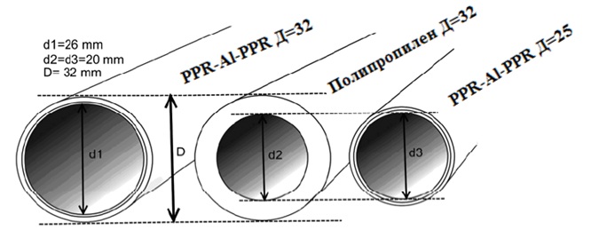
Manufacturers polymer pipes indicate the outer diameter. Therefore, in order to correctly calculate the hydraulic resistance of the heating system, two wall thicknesses should be taken away.
Accounting for local resistances in the highway
An equally important step is the calculation of the hydraulic resistance of the heating system on each section of the highway. For this purpose, the whole heat supply scheme is conditionally divided into several zones. It is best to make calculations for each room in the house.
As initial data for entering into the program for hydraulic calculation of the heating system, the following quantities will be needed:
- The length of the pipe in the section, m.
- The diameter of the main. The order of calculations is described above;
- Required flow rate. Also depends on the diameter of the pipe and the power of the circulation pump;
- Reference data, characteristic for each type of fabrication material - coefficient of friction (λ), friction loss (ΔР);
- The density of water at a temperature of + 80 ° C is 971.8 kg / m³.
In carrying out this work, it must be remembered that the smaller the selected area of heating, the more accurate will be the data of the general parameters of the system. As it will be difficult to make a hydraulic calculation of heat supply from the first time - it is recommended to perform a series of calculations for a certain interval of the pipeline. It is desirable that it had as few possible additional devices as possible - radiators, shut-off valves, etc.
To check the hydraulic calculation of a two-pipe heating system, it is necessary to execute it in several different programs or additionally manually by yourself.
Overview of programs for hydraulic calculations

In fact, any hydraulic calculation of water heating systems is a complex engineering task. To solve it, a number of software complexes have been developed that simplify the implementation of this procedure.
You can try to make a hydraulic calculation of the heating system in the Excel shell, using already ready-made formulas. However, the following problems may occur:
- The big error. In most cases, one-pipe or two-pipe schemes are taken as an example of a hydraulic calculation of a heating system. Finding such calculations for the collector is problematic;
- To properly take into account the hydraulic resistance of the pipeline, reference data is required that are not available in the form. They need to be looked for and introduced in addition.
Oventrop CO
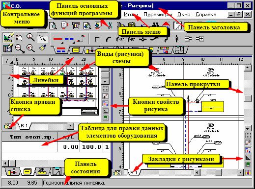
The most simple and clear program for the hydraulic calculation of the heat supply system. An intuitive interface and flexible configuration help you quickly understand the nuances of data entry. Small problems can arise during the initial configuration of the complex. It will be necessary to enter all the parameters of the system, starting from the material of the pipe making and ending with the location of the heating elements.
HERZ C.O.
Characterized by the flexibility of settings, the ability to do a simplified hydraulic calculation of heating for both new system heat supply, and for the modernization of the old. It differs from analogues with a convenient graphical interface.
Instal-Therm HCR
The software package is designed for professional hydraulic resistance of the heat supply system. The free version has many limitations. The scope of application is the design of heating in large public and industrial buildings.
Electronic assistants facilitate calculations
Through development modern technologies and engineering sciences, the effectiveness of most of the processes in human life related to machinery has significantly increased. Even one of the most complex and unpredictable sections of the communal economy - the heating system - has been thoroughly studied and inscribed in the framework of generally accepted norms and rules. Thanks to numerous studies conducted in the field of water heating, engineers were able to create a single system of information that fits into the hydraulic calculation of the heating system.
Its main purpose is to maximize the efficiency in closed circuits with natural and forced circulation. Among the tasks of calculation can be identified:
- Reducing operating costs.
- Reducing energy consumption.
- Reducing the cost of building a heating system.
- Increase of efficiency of heating of all premises.
- Ensuring the complete safety of tenants at home.
- Noise reduction to natural level.
- Prevention of destructive water hammer in confined space.
As a result of a correctly performed calculation, a significant improvement in performance is achieved, regardless of the construction scheme. The correct arrangement of the system will also give you the opportunity to forget about the need for its maintenance for many years.
However, the calculation process is not so simple - in practice it can take quite a long time. In addition, it is considered by specialists the most difficult stage in the design of the hydraulic heating of a private house.
The calculation procedure includes the following steps:
- Creating a "heat balance" of the building.
- The choice of the scheme and the main elements of the heating system - including with natural or forced circulation.
- Transferring the scheme to the axonometric projection.
- Isolation of the circulation ring.
- Determination of the required diameter of the water pipeline.
- Calculation of the hydraulic mechanism of pressure losses in individual sections of circulation.
- Execution of the linkage of parallel branches of water heating.
- Determination of the fluid flow to ensure the operability of the entire system.
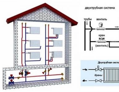
Calculations are carried out for a section with a constant diameter of a hydraulic pipeline, which has a stable capacity of the coolant. Consider the process in more detail, taking as an example the heating scheme two-story house.
Determination of the diameter of pipelines
One of the most important tasks of hydraulic calculation is to obtain data on the pipes required for use. First you have to determine what material is planned to lay the pipeline, and what its diameter should be.
Initially, the value of several indicators is known. Most experts believe that the velocity of the coolant in the system of water heating should be 0.2-0.7 m / s - with natural circulation. At a lower value of this parameter, air bubbles will form in the pipes, and with a higher noise level, there will be an increased risk of a hydraulic shock in a confined space.

The material of the pipes is of great importance when calculating their desired diameter
Optimal option is the installation of metal-plastic pipelines. They have a lower coefficient of hydraulic friction and lower pressure losses (45-280 Pa / m) in systems with natural and forced circulation. However, such an example is ideal. In practice, water-gas pipes with a loss of 60-480 Pa / m are much more often used. Having data on the heat flux, and also taking the temperature difference between the cold and hot stream at 20 degrees (for a single-tube default of 35 degrees), you can determine the diameter of the pipes in the table below.
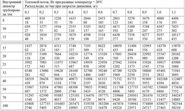
The calculation of the internal diameter of the heating pipe
It should be taken into account that it is impossible to pursue the minimization of the diameter of water heating indefinitely. When an excessively small value is reached, the velocity of the coolant in them will exceed 1.0-1.2 m / s, which will cause strong noises. Of course, for systems with natural circulation, this figure is almost unattainable, but in them the efficiency of heating can be significantly reduced.
If we consider the example chosen by us, it should be noted that in sufficiently large houses the hydraulic pump is an obligatory component of the system. Taking as the starting point an area of 200 square meters and a flow velocity of 0.5 m / s, we determine that it is necessary to stop on pipes with a diameter of 25 mm.
Attention! Table values are given for the variant using water as the heat carrier. The installation of a system with antifreeze will require carrying out independent calculations or obtaining data from its manufacturer.
Loss of pressure
When drawing up a scheme it is important to take into account all the nuances
Taking into account the pressure loss, which is especially important for circuits with natural circulation, it is necessary first to separate all the circulation rings, which represent the pipeline section leading from the boiler to the heat consumer and back. For single-pipe circuit ring is a separate riser, and for a two-pipe - each heater separately. Total pressure loss throughout hydraulic system are equal to the sum of the losses in each of the rings, which in turn decompose into losses due to friction and due to local resistances.
The first figure is half the product of the water density per square of the speed in meters per second. The second is the ratio of the length to the diameter of the pipeline, multiplied by the coefficient of hydraulic friction and added to the sum of the coefficients of local hydraulic resistances. For the calculation, formulas are used that require knowledge of the pipe roughness coefficients, but there are special tables in which you can obtain the finished number.
But if such a hydraulic calculation is of great complexity, and the manufacturer gives a ready-made figure for the specific pressure loss per meter of pipe, one can use a simplified formula in which the ratio of the coefficient of friction to the diameter of the pipe is replaced by a constant. Such a calculation scheme is most often used for single-pipe heating, when the accuracy of the final indicator is not so important.
In addition, the use of a simplified coefficient is also fully justified when natural circulation coolant. In our example we will add additional data - the length of a conventional steel pipeline is 100 m, the diameter of the pipe is estimated, the local losses are equal to 800, the number of sections is 1, the table resistance is 1.02. In this case, the losses will be equal to 1.02 * 100 * (971.8 * 0.5 2) / 2 + 800 = 13190.5 Pa.
Attention! The sum of the local coefficients of hydraulic resistance also includes the values of all the stop valves, heating appliances, expansion tanks and compression equipment.
An example is a boiler, pump, expansion tank, adjustment valves, radiators, needle valves, bypasses, etc.
Binding of contour rings
Connection to the pipeline
The effect of the laws of physics leads to the fact that at the points of alignment of the rings the magnitude of the pressure loss will always be the same. If you look at the example of the water circuit of our two-story house and assume that there are 20 rings of different diameters located at different distances from the boiler, then everyone will see different pressures and different speeds of water movement. For a system with both natural and forced circulation, this is a significant disadvantage, which will require resolution to ensure maximum efficiency.
Alignment for the system of these indicators, obtained as a result of the above calculation, is performed with the help of manual or automatic control-stop valves. In the field of manual water-fittings, the best example is the products of Stromax. And automatic, which is ideal for systems with forced circulation - HERZ. To obtain the maximum result, radiator thermostatic water heating valves are used, which are combined with balancing valves located as close to the rings as possible. In this case, the system will operate in dynamic mode of automatic adjustment.
Recently, the autonomous heating system has become increasingly in demand. Most apartment owners refuse central heating, counting individual system more reliable and qualitative. At the same time quite often the main reason for choosing an autonomous heating system is its availability and economy. Of course, initially to purchase necessary equipment and the installation of the system will have to be spent. However, all costs pay off fairly quickly, since in the future maintenance of such a system is much cheaper than a monthly payment for central heating. Of course, the economy of an autonomous system is achieved only if it has been properly selected and installed. In this regard, the huge importance is acquired by the hydraulic calculation of the heating system, which must be carried out in advance.
What is it for?
First of all, it should be understood that the old program for monitoring the functioning of the heating system differs significantly from the modern one precisely because of the different implementation of the hydraulic regime. In addition, modern heating systems are characterized by the use of better materials and installation technologies - which is also reflected in their cost and economy. Moreover, the modern system allows you to make control at all stages and notices even a slight temperature fluctuation.
You can draw a simple conclusion: the application of a better, modernized modern system allows significantly reduce the level of energy consumption, which, in turn, leads to an increase in the economy of the system. However, you should not install the heating system yourself, because this process requires special knowledge and skills. In particular, problems are often caused by an improperly installed skeleton and a failure to perform a hydraulic calculation of the heating system. What is important to consider when installing the system:
- only in the case of a correctly executed installation will a uniform flow of coolant to all elements of the system. And this indicator is the guarantee of equilibrium between the regularly changing temperature of air outside and inside the room.
- minimization of the cost of operation of the system (in particular - fuel) leads to the fact that significantly reduces the hydraulic resistance of the heating system.
- the larger the diameter of the pipes used, the higher the cost of the heating system.
- the system should not only be reliable and qualitatively installed. An important factor is its noiselessness.
What information do we get after the hydraulic calculation of the heating is done:
- diameter of pipes, applicable at different parts of the system for its maximum effective operation;
- hydraulic stability of the heating system in different segments of the heating system;
- type of hydraulic piping bundle. In some cases, to achieve maximum balance of individual processes, a special frame is used.
- flow and pressure of the coolant during circulation in the heating system.
Of course, calculating the hydraulic resistance of a heating system is quite a costly process. However, it should be borne in mind that the correctness of its implementation makes it possible to obtain the most accurate information necessary to create a high-quality heating system. Therefore, the most appropriate is to hire a specialist, and not an attempt to make this calculation yourself.
Before the hydraulic calculation of the heating system is carried out online, you should obtain the following data:
- balance of heat indicators in all rooms, which will need to be heated;
- the most suitable type of heating devices, draw on the preliminary plan of the heating system their detailed arrangement;
- determination of the type and diameter of pipes used for installation;
- the development of a plan for the locking and directing skeletons. In addition, it is important to think over the details in the system of all the elements - from heat generators to valves, pressure stabilizers and sensors for monitoring the temperature of the coolant;
- creation of the most detailed plan of the system, which will indicate all its elements, as well as the length and load of the segments;
- determine the location of the closed loop.
Example calculation of heating hydraulics
Here is an example of a hydraulic calculation of a heating system. We take a separate section of the pipeline, on which there is a stable heat loss. The diameter of the pipes does not change.
Determine this area follows, based on the data on the heat balance of the room in which it is located. It is important to remember - the numbering of sections starts from a heat source. Mark the connecting nodes that are present on the flowing part of the highway in capital letters.
If there are nodes on the highway, they should be marked with a small stroke. We use Arabic numerals to determine the nodal points that are present in the sections of the branch. With a horizontal heating system, each of the points corresponds to the floor number of the building. In case of application vertical system the value of the point corresponds to the value of the riser. The nodes in which the flow is collected should also be marked with dashes. It should be noted that the numbers must necessarily consist of two digits. The first of them means the beginning of the site, and the second one, respectively, is the end.
In the case of a vertical system, the numbering of risers should be made in Arabic numerals, following the clockwise direction.
To determine the length of all sections of the pipeline, a pre-compiled detailed cost plan should be used. At its creation it is necessary to adhere to the accuracy of 0.1 m. At the same time, the heat flux of the section in which the calculations occur is equal to the heat load given by the coolant in this segment of the system.
 Indicators of the hydraulic calculation of the design circulation circuit, taking into account the pressure loss for local resistance in the sections
 Using programs
In the process of modeling a new building, the most rational is to use a special program that as accurately as possible determines the thermal and hydraulic characteristics future heating system. And you can use the excel program. The program provides such data.