The TV socket is single and terminal. TV socket: rules and wall mounting option
Before you start repair work in the apartment, it is necessary to plan the design of future premises. An important aspect of this issue is planning the placement of furniture, interior items, as well as household appliances. First and foremost, this is due to the need to optimally split the electrical wiring and install it in the right places, including television. To properly connect the outlet for a TV it is enough to know its device, general principle work and the order of installation.
Coaxial cable assembly
The main difference, which determines the difference between the electrical and television sockets, is the structure of the cable connected to each of them. If the standard electric wire represents two or three separate veins, covered with insulation, which are connected to the corresponding contacts of the socket using bolted connections, the design of the antenna cable is somewhat different.
The television coaxial cable is very easy to identify in appearance. It is a fairly thick wire of circular cross section, having inside a single solid conductor core made of copper. This central conductor is covered with a dense layer of insulation, on top of which is a screen of aluminum foil and thin steel wire. In most cases, PVC insulation is used as the outer protective coating of the cable.
Low-quality manufacture or damage to any of the antenna wire elements leads to a significant deterioration in the signal quality, therefore, the lining of such lines should be treated with the utmost responsibility.
Let's consider in more detail the device and purpose constituent parts tv cable:
- Insulation. It is made of dielectric (as a rule, polyethylene), serves to exclude galvanic connection between a current-carrying vein and the screen.
- Screen. In any coaxial cable, this element is designed to prevent the emission of a high-frequency signal into space. Its other function is protection against electromagnetic interference, to which the transmitted signal is very sensitive. In addition, to ensure the flow of high frequency current requires two wires, so in this case the screen is used as a second conductor. Such a cable is called asymmetrically shielded.
- A current-conducting vein. It is the main part of the design, since it serves to transmit an electrical signal.
- Outer shell, which is designed to protect current-carrying parts from mechanical influences.

As can be understood from the design of the cable, its connection to a television outlet is the connection of the central conductor and the screen to the corresponding contacts. In order to understand the features of connecting such wires, it is necessary to briefly review the design and purpose of the main parts of the television outlet.
It should also be noted that when laying the antenna cable, do not place it in the vicinity of the electrical wires.
When connecting consumers of electricity, there are strong enough magnetic fields around current-carrying conductors of power wiring elements. Such fields can greatly distort the transmitted high-frequency TV / SAT signal. In addition, some household appliances have the ability to emit electromagnetic waves, which also affect the quality of the tv signal. And although at the present time such devices are becoming less and almost all models of modern TVs are equipped with special filters that to some extent eliminate such influence, nevertheless, the possibility of interference is worth considering. For example, Legrand does not recommend placing power cables closer than 2 cm from the antenna cable.
As for the manufacturers of equipment used for installation electrical networks and information transmission systems, then, of course, one of the leaders in this market is the French company Legrand. Today it has representative offices in more than 60 countries of the world, and in the territory of our country Legrand has been supplying products since 1980.
To date, a wide range of electric and television Legrand sockets, switches, splitters, adders, amplifiers and other electrical products are presented in electrical stores. The high quality of all Legrand devices provided them with widespread recognition, however, when buying such equipment, one should beware of fakes.
Kinds of television outlets
Depending on the purpose and use in the wiring diagram of the tv cable in the apartment, the sockets are divided into three main groups:
- Single. The simplest in design and common devices. They are used to connect one TV set to a splitter or antenna.
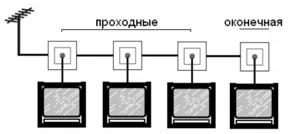
- The terminal. Used for installation at the end - a serial connection of outlets. Do not confuse this device with single sockets. For stable operation of any of the tv Legrand outlets in the loop there must be a certain wave resistance of the line, which creates an end TV socket.
- Passing. They are designed to be installed in the middle of the loop. The design of these devices provides for connecting the antenna wire from both sides to them. One of these wires is coming, it comes from the previous device connected to the splitter, and the other - outgoing (used to transmit the signal to the next outlet).
TV outlet device
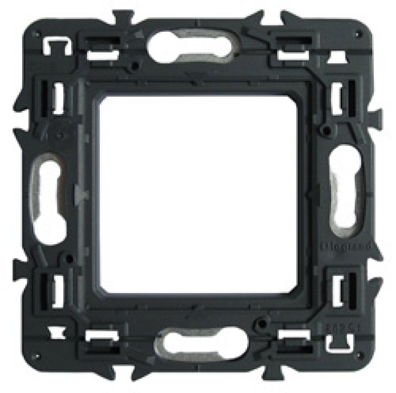
The main parts included in the design of any TV socket are:
- The housing is a tv outlet (or printed circuit board), which is designed to connect the antenna cable to it. In a single outlet this part has no electronic circuits and serves only to ensure a reliable contact between its elements.

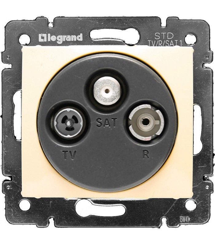
- Front panel. This element of the device design performs not only a protective, but also a decorative function. It can be chosen in such a way as to maximally match the interior of the room. Depending on the purpose of the Legrand outlet, additional outputs, such as SAT and R, may be present in it. The TV-R-SAT socket connection is performed using one cable coming from a special adder.
![]()
- Support. It is used for fixing all the elements of the socket design to each other, and also securely fixing the device in the mounting box.
Connecting the TV socket
To connect such an outlet, you must adhere to a simple algorithm:
- Prepare and install. For the installation of devices of the built-in type, which are the most common at present, it is necessary to drill a hole for the box in the wall. In addition, to lay the antenna cable, suitable for such an outlet, you will have to bend the wall. These works are associated with the appearance of a large amount of dust, so they try to coincide with the repair in the apartment.
- Prepare the cable. For this, it is necessary to remove the protective coating layer approximately 3 cm from its end. Next, you need to gently release the central conductor from the insulation at a distance of 1 cm from the edge.
- Separate the housing from the front panel and the support.
- Connect the central conductor to the corresponding terminal of the housing with a screw connection.
- The cable shield is fixed with a special clip, while ensuring their reliable electrical contact.
- Connect the card to the support and fix the whole structure in a pre-assembled box.
- Install the front cover of the tv outlet.
- Connect the antenna wire from the TV to the corresponding socket of the outlet (TV-R-SAT)
It should be noted that there are designs of television outlets, the way of attaching the antenna wire to which may differ slightly. For example, in Legrand sockets can be used hinged or spring fasteners. In any case, the basic principle of connection remains unchanged.
Connecting a group of TV outlets
It has long been a normal occurrence for two or more TVs in one apartment to be able to receive a signal from a cable television (TV) provider or from a satellite antenna (SAT). In order to properly connect TV sockets Legrand, you can use the following scheme.

The connection diagram of the TV outlets shown in the figure is called the "star connection" and has several advantages:
- Slight attenuation of the signal.
- Since all the wires come out of one place, it is convenient to place the input box in it.
- It is not necessary to use an excessive number of feedthrough sockets, which positively affects the signal quality.
- The malfunction of one device does not affect the performance of all the others.
In this scheme, the TV outlets are connected through a special device called a splitter. It is designed to divide the tv or SAT signal into equal parts, transmitted to individual devices without losing its quality. This is not the only type of splitter used to lay antenna cables. Another common type of these devices is TAP. The main difference lies in the fact that the splitter divides the signal into equal parts by the number of subscribers and can be used as a signal summator. As for the TAP type splitter, it separates some part of the tv (SAT) signal and transmits it to the number of pins provided by the design.
When choosing a splitter, you should pay attention to its frequency characteristics. There are two main types of these devices:
- Splitters intended for installation in digital television networks. They have operating frequencies not exceeding 1 GHz.
- Splitters for satellite antennas (SAT). And the operating frequencies lie in the range up to 2.5 GHz.
Another important criterion for choosing these devices is signal attenuation. If possible, it is necessary to install a splitter that has this parameter minimal in the frequency range used.
If the signal from the provider or tv antenna is too weak or the TVs to which it is intended to transmit are too many, then you need to take care of installing the amplifier (for example, the SAT Legrand amplifier).
Another way to connect is to use sequential circuit, an indispensable element of which is the outlet socket.

This scheme provides for a serial connection of the feed-through sockets, the last of which must be the final one. It should be noted that with such a connection there is some attenuation of the signal, so it is undesirable to use a large number of elements. The advantage of such a scheme can be called substantial cable savings.
At any modern apartment at least two TV sets are installed. To ensure that every member of the family can safely watch your favorite films and programs in your room, you need to install television outlets on the premises.
TV outlet features
TV socket Legrand allows you to install several receivers, without wrapping the apartment wires. This compact electrical device divides the signals different types and does not allow interference in the network. Depending on the number and location of televisions in the house, installation of three types of sockets is possible:
- Single socket for TV. It is also called simple or individual. The device has a minimum impedance, so interference is possible on the screen.
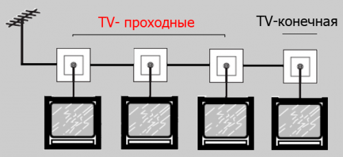
- Feedthrough TV socket . It becomes a link in the chain. This outlet has an input for the cable, an output for connecting the TV and an output to the next outlet. It should be borne in mind that with this connection scheme, signal attenuation occurs.
- TV outlet terminal . The impedance of the device is in line with the resistance of the line, 75 Ohm. This outlet for the television cable is mounted at the end of the circuit, that is, it will be preceded by a passing device.
Which TV outlet to buy
To determine the type and quantity TV-outlets Valena , which you need, you need to choose the scheme for connecting TVs. With single options everything is clear: one device is one TV socket (by the way, it can be not only simple, but also terminal). But the television network in the apartment can be mounted according to one of two options:
- The "star" scheme. Several outlets are connected to one splitter. The circuit requires a large cable flow, but is characterized by a minimum attenuation of the signal. Here you will need terminal or simple tV sockets Quteo by the number of connected televisions.
- Pass-through circuit, or plugging. The TVs are connected in series. It will take one terminal socket for a TV antenna and a few walk-throughs.
Do not worry that with the daisy-chain connection, the last TV will not be good to show. Signal level of modern cable television and thoughtful design kaptika (or other model Legrand) provide a quality picture of all connected screens.
Sockets for TV antennas have become increasingly popular. After all, they make it possible to hide engineering networks and greatly simplify the connection of video equipment to it.
At the same time, these outlets have a rather attractive appearance, they allow you to create your own local area network for television, and also reduce the level of interference in such a network.
Connecting TV outlets
Before approaching the issues of selecting and connecting TV outlets, you should understand the possible connection schemes. After all, the subsequent choice will largely hang from the connection scheme, as well as the type of signal for which the socket is designed.
At this time, the installation of a TV socket can be performed in two ways. This is a walk-through diagram and a star diagram.
Connection of TV outlets through the pass-through circuit
The connection of the TV outlets through the pass-through circuit does not require additional equipment and is generally less expensive. After all, each subsequent socket is connected from the previous one, which allows you to save a lot on the cable.
So:
- Especially for such a scheme, almost all manufacturers produce pass-through sockets. Which allow you to connect a suitable and outgoing cable in one socket box.
- Such a socket for a TV antenna is a very suitable solution, but for modern cable and satellite networks, a pass-through scheme is practically not used. There are several reasons for this at once.
- One of the main ones is a sufficiently strong drop in the signal at such grommets. At different manufacturers it varies from 10 to 15 dB. It's clear, the lower this indicator, the better.
Note! According to the European standards CENELEC EN 50083-7, the signal level should be within 57-74 dB. Our GOST 28324-89 requires a signal level in the range of 57 - 83dB. Therefore, the drop in the signal level by 10-15 dB on one pass-through socket may have a very negative effect on the image quality of subsequent televisions.
- Another weighty argument is the almost complete impossibility of using pass-through circuits when connecting satellite - SAT TV.
Connecting TV outlets according to the star scheme
A TV socket connected by a star circuit must necessarily be non-terminal and not through. If you have one output for a TV signal, then these outlets are called single or simple. If you have connectors for radio and (or) satellite TV, the manufacturers call them - in terms of topology, the star.

So:
- The star schema assumes the presence of a splitter or as it is also referred to as a signal unwinder. It is installed on a suitable cable from the antenna, satellite or cable TV. Some splitters have the ability to connect two or even three suitable cables.
Note! Splitter (TV crab, antenna divider, TV divider) provides the signal transmission from one suitable cable to all output channels. At the same time, the signal level drop for different manufacturers is from 10 to 15 dB. It has shielding from external and internal interference, which ensures high quality of the signal on each of the outgoing channels.
- If necessary, an amplifier can be installed before the splitter. It will increase the signal level on all channels that depart from the breeder. If necessary, an amplifier can be installed on each suitable cable.
- A splitter for an outlet can have a virtually unlimited number of outputs. Each of them must end with a single TV socket.
- This connection scheme ensures an even signal level for each TV. If one line is damaged, the others work in normal mode.
- Out of the shortcomings of the star connection scheme, only the price can be marked. After all, the use of additional equipment and more cable significantly increases costs.
Types of sockets
Now knowing the connection diagrams, you can look more closely at the types of TV outlets and their purpose. After all, for each scheme you need to purchase only a certain type of sockets. Buying out other types of sockets can significantly reduce the quality of the signal.
Single socket or socket according to star typology
The device of a socket of a television made in the topology of a star has the simplest design. Therefore, we will begin our analysis with it.

- This outlet has a connector for connecting a single power cable. There are clamping or screw terminals for mounting. In some cases, the center conductor has clamping terminals, and the shielding braid has screw terminals.
- The drop in the signal level in such outlets does not exceed 1 to 3 dB. This is achieved due to the fact that the filter of the uncoordinated or reflected signal is located on the splitter. Due to this, the signal drop occurs only due to switching interference at the junction.
Pass-through sockets should solve a whole range of problems. They should provide a sufficient level of signal on this outlet and a minimum signal drop on subsequent outlets. Therefore, their design is much more complicated.

- The access socket has two connectors for a suitable and an outgoing cable. The contact part of the socket can be made with screw, clamping or mixed terminals. Thanks to which you can connect the cable with your own hands.
- The drop in the signal level for such an outlet is the same as 1 to 3 dB. But here there is some feature. The fact is that the signal drop on the outgoing cable can be from 10 to 15 dB.
- This is due to the fact that in the pass-through circuit it is necessary to provide filtering of the reflected signal. To do this, the socket provides a special resistance capacitive or resistor type. It reduces the level of interference at all outlets in the circuit.
The outlet socket is often confused with a single socket. But structurally they are somewhat different. And it's not just the installation site.

So:
- The installation instruction for the terminal outlet assumes that it is used only as a loopback end point. In this case, the contact portion of the socket is visually indistinguishable from the contact portion of a single outlet.
- The drop in the signal level at this outlet is due only to the transient resistance and is 1 to 3 dB. But here there is the same feature that is characteristic of the pass-through sockets.
- A TV connected to such a receptacle outputs a reflected signal which, in the form of interference or an overlaid image, may appear on neighboring TVs in the circuit. In connection with this, there is also a filter of uncoordinated signals. The losses on it are 10 - 15 dB.
Single sockets with two leads and other types of TV outlets
Separately, I would like to consider single or simple sockets, which contain two inputs for the cable. This somewhat puzzles potential buyers and it seems to them that they want to be deceived.
- The matter is that many manufacturers let out single sockets on two feeding cables. The second cable serves as an additional power source.
- Suppose you had a socket for a TV antenna. But you decided to connect satellite TV. In order not to alter the entire TV network, you simply can connect the second cable to the outlet. However, due to frequency separation, the signals will not interfere.
- Separately I would like to note double sockets TV-R (TV-FM), as well as triple TV-R-SAT (TV-FM-SAT). To connect these outlets one or two cables are used. Due to the different frequency of the signal, they divide the signal into a television, radio and satellite signal.
- So the outlet for the TV cable transmits signals with a frequency of 5 - 68 and 120 - 862 MHz, the radio output transmits signals in the frequency of 87 - 108 MHz, and the satellite signal is transmitted in the frequency range 950 - 2400 MHz. Thanks to this you can maximally unify your TV outlet.
Conclusion
As you can see, to create your own TV network in an apartment, the main thing is to think and organize everything correctly.
After all, the process of connecting TV outlets is not so complicated and is described in sufficient detail in our previous articles. The main thing is to choose the sockets correctly and the connection scheme and then you will not have any problems with the quality of the TV signal on the TV.
The principles of installing sockets for TV and conventional connectors are similar, since in both cases the same type of juniper is used. There are only minor differences in the way the installation works. In this article, we will take a closer look at how to connect a TV socket.
Varieties of TV outlets
There are two types of TV outlets: the final (end) and through. Also the connectors are classified according to their purpose: for terrestrial TV (designated as TV), for radio (R), for satellite TV (SAT). In addition, there are combined types of outlets: TV (45-1000 MHz), TV + R (92-108 MHz), TV + SAT (950-2500 MHz), TV + R + SAT.
Advice! It is desirable that the socket is the same color as the power connectors - so it will be easier to fit it into the interior. If the sockets are installed in a single unit, then not only the color, but also the device manufacturer should be the same.

The final connectors are named because they are the final node on the network. This type of sockets is distinguished by a signal of increased clarity, no interference due to a wave resistance equal to 75 Ohm. Terminals can work with several standards: individually or in combination (TV, TV + R, TV + R + SAT).
Another type of connectors is a through-outlet TV socket. Such devices are used to receive a signal and then transport it to other points of connection. The signal transmission between the sockets is carried out via a coaxial cable. The device is equipped with a pair of jacks (the socket at the input and output). The TV is connected at the input, and on the output there is a wire going to the other consumer. In this case, the last socket in the circuit is always final. Passing connectors are not used to build circuits in which the satellite signal is distributed due to technical incompatibility with most of the solutions.
 The pass-through TV-outlet does not differ from the terminal one from the front panel. But on the back side there are two connectors with arrows input and output
 Connection diagrams
There are many schemes for connecting a tv-connector. A splitter is used to process the signal. This device looks like a small box and performs the function of signal splitting. Just like in telephone lines, transmission of digital electrical signals can not do without their separation.
The principle of the splitter is to divide the signal into identical packets. Further, the divided segments are transmitted to the input part of the television connectors. The splitter is designed in such a way that for all TVs receiving the signal, regardless of their number, a signal of equivalent quality will be transmitted. As a result, within one apartment there is no sense in a separate antenna for each TV.

Connection can be made in one of two ways:
- Scheme "asterisk", when the old cable is removed, and the new one is laid through the splitter.
- Daisy chain.
Below, we will look at the question of how to plug in an outlet, while paying attention to the merits of the schemes in question.
Scheme "star"
In this scheme, a splitter is used that performs the function of splitting the signal, splitting it into packets, and amplifying it. The device is placed at the entrance of the cable into the living room from the entrance. Next, wiring for users of antenna conductors is carried out. Installation of TV sockets using this simple technology is most often used, because the splitter provides a number of advantages:
- The cable is located in a technically protected place, which is important both for installation work and for further preventive inspections.
- The signal is stable.
- Divided signal packets are delivered uninterruptedly to all TV receivers in the apartment.

Daisy-chaining
This method of installing a TV socket involves the use of a loop. The main cable is routed to any of the TVs in the house, and then routed to other receivers directly on the connector. The layout is a branch to two or more parts (depending on the number of TVs available).
The connection in this way is called a loop. In this case, the connectors connected by the loop must be through, except the last, which is the end.
The ribbon circuit allows you to save on the cable consumption, but it also has disadvantages. The drawback of the loop system is that the quality of the first receiver will be higher than in the subsequent receiver. However, with sufficient strength of the television signal, the difference will be almost imperceptible. In addition, it is necessary to take into account the fact that modern television technology is equipped with the possibility of signal amplification, and this happens in automatic mode.
 Daisy-chaining through a through-outlet television outlet
 So, the uneven distribution of the signal in this case can be considered an insignificant drawback. Among the other drawbacks of the loop system are:
- Scheme, where there are through-going and terminal TV outlets, will cost more than the standard "star" scheme.
- In the event of a circuit break, all subsequent consumers are deprived of a television signal.
Schneider outlet installation
As an example, we will analyze the installation of a pass-through outlet from the French company Schneider Electric (model of a tv rj45 outlet). The task is to connect two TVs to one cable through a loop loop.
When installing the sockets for a tv cable, we provide for a small excess of the cable itself - it must go out from the back box. Next, clean a small area of insulation material on the cable. At the same time, we preserve in integrity the central core and the shielding braid.

We start by removing the front panel, loosen the tightening screw a little. This is necessary to ensure that the cable is free to exit through the hole.
There are arrows on the connector housing. We insert the cable to the end in the direction indicated by the arrows. Then press the cable with the clamping screw (we twist it). The cable must be securely fixed, but the screw must be twisted with care, so as not to transmit the highway. With the second end we perform exactly the same manipulations. The connector is installed in such a way as to avoid bends on the cable.

Note! Before installing the TV socket, inspect the cable fixing section for the possibility of shorting the main conductor with a braid.
When the cable is inserted and fixed, put on the front panel. Fixing the panel is carried out with the help of special branded latches. We check with a building level the accuracy of installing the connector horizontally. If everything is in order, finally fix the fixing bolts to the panel and close it with a frame.
Connecting the Lezard connector
Outlets from the company "Lezard" are inexpensive and are of good quality. However, when choosing the product "Lezard", you need to consider the presence of a printed circuit board on it. The fact is that the boards are equipped with a component such as a capacitor. This part is next to the central core lock and the cable connection. The capacitor is impermeable to the supply voltage, which must be supplied to the active antenna. Therefore, these connectors are suitable only for passive antennas.
If nevertheless there is a desire to adapt such a socket to the active antenna, you need to put a standard conductor instead of a filtering capacitor. This is done by shorting and sealing a piece of copper wire instead of a condenser.
The very connection of the TV socket consists in the installation of the signal conductor of the TV cable in the center female terminal. Also, you need to lock the screen with a bracket.
Note! Do not allow the main conductor, which skips the signal, to short-circuit with a braid. Otherwise, the screen will be broken, preventing the loss of the television signal in the cable.
Connecting the Legrand connector
TV outlet from the French manufacturer "Legrand" is easy to connect, but also quite expensive.
When connecting the connector, fix the central cable core in a special spring clip. Press the foil braid against the body with a flap.
We remove the cover of the fastening, which covers the connecting areas of the coaxial cable. To do this, gently pull the cover with a screwdriver, thereby releasing the lock.
We remove the outer insulating layer and the inner dielectric material of the cable by about a centimeter in length. We guide the cable into the connector, and fix the copper core with a self-clamping terminal.
Note! The contact of a braid with a female casing is achieved thanks to a plate that connects to its external insulator, firmly pressing against the cable shield.
When the cable is connected to the connector, install the latter in the jar. We fix the socket with a pair of screws. Then tighten the screws with the spacers of the socket retainers. We twist the scraper screws to the stop. We place the front panel of the connector on its proper place. The TV wall outlet is installed and ready for use.
At the moment, TV outlets are quite widely represented on the market and are increasingly used. At the same time, it is often enough to find complaints about their work and the quality of the television signal transmitted by such outlets.
But in most cases these complaints are groundless, and the low quality of the signal is due to the wrong choice of the sockets themselves. Therefore, in order not to be disappointed in this electrical installation equipment and not throw money away, let's look at this issue.
Schemes for connecting TV outlets
First of all, let's consider possible options schemes for connecting TV outlets. After all, the subsequent choice of the type of TV outlets for installation directly depends on this. At the moment, the connection schemes are actively used - through type and according to the star scheme.
Pass-through circuit
Let's start with less commonly used, but cheaper and simpler in terms of installation of the pass-through scheme. The essence of this scheme is serial connection all TV outlets with the subsequent connection to the first of them antenna.
So:
- The main feature of this circuit is that for each subsequent outlet the previous one is the source of the signal. In this regard, there are certain problems associated with both the level of the signal drop and the need to reduce the level of the reflected signal.
- In order to meet these requirements, a television outlet and a wall outlet are used. The end socket is installed at the end of this loop, and all other TV outlets in the loop must be through.
- The main disadvantage of this type of connection is the decrease in the signal level at each subsequent outlet. So usually the signal level drop on each subsequent outlet is at least 13 - 15 dB.
Note! According to GOST 28324-89 the signal level should be 57 - 83 dB. That is, even at the maximum level of the received signal the installation of more than two pass-through sockets will reduce its level below the maximum permissible values. In this regard, it is likely that the image quality will decrease.
- The terminal end is not an exception and the signal level drop on it is nothing less. The fact is that a special circuit is used to reduce the level of the reflected signal, which suppresses this signal. A side effect of this suppression is a reduction in signal strength. If it is "bitten off", as some craftsmen suggest, then the effect of overlaying images of different TV sets in the cable is likely.
- Not a disadvantage, but a weighty restriction, is the impossibility of using a loop-through scheme to create a digital television network. In connection with this, the tv outlet and throughput outlet with SAT output, intended for satellite digital TV, will not be effective. At the same time, terminal sockets are actively used in digital TV, if this is the only outlet connected to the receiver.
Star schema
To implement the so-called "star" scheme, in addition to directly sockets, you will need a splitter or as it is also called a signal multiplier. The price of this device is not so high, but the signal level in all outlets will be the same.
In addition, in most cases it comes with a built-in amplifier, which allows you to achieve the ideal signal level.

So:
- For the "star" scheme, our instruction recommends the use of only single sockets. Moreover, their cost is slightly lower than for other types of TV outlets. This is due to the fact that there are no additional schemes in them. In fact, interference cancellation takes place in a splitter and is not needed directly in the socket.
- The level of signal drop in such outlets usually does not exceed 1 to 3 dB. And by and large this fall is associated only with switching processes. Therefore, if the connection is performed qualitatively, then such losses can generally be neglected.
- The main drawback of the "star" scheme is its higher cost and complexity of installation. It is associated with the installation of additional equipment and the need to lay more TV cable. But as they say, quality requires sacrifice.
Note! When installing a television network according to the "star" scheme, it is not recommended to lay TV cables in one shrot. In addition, it is desirable to separate the television cables from the power equipment. After all, power wires can not only interfere, but even damage can damage the entire television network, and in the worst case all connected TVs.
Selection and connection of terminal outlets
As you can see, just figuring out the connections for TV outlets we decided where and when the end-point TV socket is used and what is the difference from the TV outlets of other types. Now it remains to decide what to look for when selecting and how to connect such electrical installation devices.
Selection of TV outlets
First of all let's define with those parameters on which it is necessary to pay attention at a choice of an end TV socket. We have already mentioned some of them, but now let us dwell on them in more detail.

So:
- Each outlet has a certain level of the input signal drop. This is due to both the switching processes and the way the wire is attached to the outlet. At the moment, screw and clamping methods are used and which one is better definitely not to be said. But the level of loss to pay attention to, you can usually drop the signal level is about 1 - 3dB.
- But as we have already mentioned, the terminal socket contains a so-called filter. On it, the signal level drop is much higher and usually ranges from 10 to 15 dB. If this value is lower, then the quality of this filter should raise questions for you.
- As you know, video and audio signals can be transmitted in a wide range of frequencies, which is limited by standards. So the most common is EN500837. It regulates the parameters in the frequency range of 30 - 2150 MHz. Our GOST R 52023 defines parameters in the range from 40 to 1000 MHz. But the standard DOCSIS v.2.0 extends to frequencies from 47 to 862 MHz. Typically, the range of TV socket frequencies meets one of these standards.
- Well, the last parameter on which it is worth paying attention is the reliability of the fasteners and the appearance of the outlet. The use of poor-quality plastic is often the result of little-known manufacturers. In addition, pay attention to understandability for you how to fix the cable. After all, many well-known manufacturers produce sockets with light, but "zamadrenymi" methods of installation.
Connecting the Socket Outlet
Well, finally it comes to the question of connecting the terminal TV outlets. To perform this action is quite possible with their own hands and special knowledge is not required for this. Yes, and a special tool, too.

So:
- For connection, first we clean the cable. How to do it correctly you can see in the photo.
- Now directly on the socket unscrew the clamping screws. We insert the cable and check that the braid is not in contact with the central core. After that, we pinch the cable. This completes the connection.
- Some manufacturers have tried to simplify the installation of the outlet as much as possible. For this, there are various clamping fixtures. So the manufacturer of Legrand offers TV sockets with a clip based on the reclining lock, some offer spring clips and so on. To describe each of them is practically not realistic. But all of them are based on the secure attachment of a separate cable braid and a separate core core.
Conclusion
The terminal TV sockets are fairly simple to install and do not require specific knowledge. But to achieve high quality pictures it is very important to choose the right outlet.