Membrane tank for water supply - selection of the optimal model and installation example. Service of the aqua accumulator tank, or whether it is possible to pump up the membrane expansion tank without draining the water from the system
The autonomous water supply system today does not surprise anyone. Such structures are very convenient and practical, however, for their operation, often, devices are required, of which a person using only a centralized water supply may simply not know. For example, an autonomous water supply system will operate continuously for a long time only if an expansion tank for water supply is included in it. Modern industry produces many different models of such devices. To choose for yourself the best option, it is necessary to be guided in the types of equipment and well aware of the principle of its operation.
The device and functions of this equipment
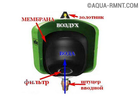
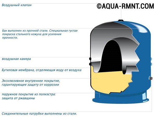
Expansion tank is designed to maintain pressure in the water supply system. Most often, closed equipment is used for water supply membrane type. It is a container inside which a rubber membrane is mounted. It divides the device into two chambers: air and water. After starting the system, the electric pump fills the latter with water. The volume of the air chamber decreases. The smaller the volume of air in the tank, the higher the pressure.
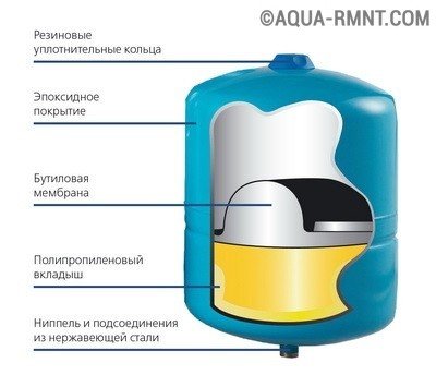
As an expansion tank for the water supply system, a membrane type construction is used. The rubber diaphragm divides the device into two chambers: air and water
As soon as it exceeds the programmed mark, the pump will be automatically switched off. It will only turn on after the pressure has dropped below the minimum programmed mark, with water coming from the tank's waterbox. The "turn-off" cycle is repeated automatically. The pressure in the system can be checked using a pressure gauge that can be installed on the equipment. The device can be adjusted by selecting the preferred working pressure range.
The membrane expansion tank installed in the water supply system performs several functions at once:
- Maintains pressure when the pump is off.
- Protects the system from a possible hydraulic shock, triggered by voltage fluctuations in the network or air in the pipeline.
- Keeps under pressure some water.
- Protects pump equipment from premature wear and tear.
The use of the expansion tank makes it possible to not include the pump at low water consumption, but to cover the demand for water at the expense of the liquid stored in the tank.
Types of membrane tanks
There are two main types of expansion membrane equipment.
Device with replaceable diaphragm
The main distinctive feature is the possibility of replacing the membrane. It is removed through a special flange, which is supported by several bolts. In this case it should be taken into account that in large-volume devices for stabilizing the membrane it is additionally fixed with the rear part to the nipple. Another feature of the device is that the water filling the tank remains inside the membrane and does not come into contact with the inside of the tank. That protects metal surfaces from corrosion, and the water itself from possible contamination and significantly extends the life of the equipment. Such models are produced, both in horizontal and vertical versions.
Devices with a replaceable membrane differ more long service, because the most vulnerable element of the system can be replaced and the water does not come into contact with the metal case of the device
Device with stationary diaphragm
In such devices, the inner part of the tank is divided into two parts by a rigidly fixed membrane. It can not be replaced, therefore, if it fails, the equipment will have to be changed. In one part of the device there is air, in the other - water, which directly contacts the internal metal surface of the device, which can provoke its rapid corrosion. To prevent the destruction of metal and water pollution, the inner surface of the water part of the tank is covered with a special paint. However, such protection is not always durable. Devices of horizontal and vertical types are produced.
A version of the device with a rigidly fixed membrane. The design assumes that the water is in contact with the walls of the equipment
How to choose the right device?
The main characteristic on the basis of which the equipment is selected is its volume. It is necessarily taken into account such factors:
- Number of people using the water supply system.
- Number water intake points, the number of which includes not only shower and faucets, but also household appliances, for example, washing and dishwashers.
- The probability that water will be consumed by several consumers at the same time.
- Limit number of "start-stop" cycles per hour for installed pumping equipment.
- If the number of consumers does not exceed three people, and the installed pump has a capacity of up to 2 cub. m per hour, a tank of 20 to 24 liters is chosen.
- If the number of consumers is from four to eight people and the pump capacity is within 3.5 cubic meters. m per hour, a tank of 50 liters is installed.
- If the number of consumers is more than ten people and the productivity of pumping equipment is 5 cubic meters. m per hour, select the expansion tank per 100 liters.
When selecting the correct model of the device, it should be taken into account that the smaller the volume of the tank, the more often the pump will turn on. And also the fact that the smaller the volume, the greater the probability of pressure jumps in the system. In addition, the equipment is also a reservoir for storing a certain water reserve. Proceeding from this, the volume of the expansion tank is also corrected. It should be noted that the design of the device allows the installation of an additional reservoir. And this can be done during the operation of the main equipment without labor-consuming dismantling. After installing a new device, the volume of the tank will be determined by the total volume of the volumes installed in the system.
Besides technical specifications choosing an expansion tank, special attention should pay to its manufacturer. The pursuit of cheapness can result in much more substantial expenses. Most often, the cheapest materials are used for production of attractive models, and, as practice shows, they are not always of high quality. Especially important is the quality of the rubber from which the membrane is made. From this directly depends not only the service life of the tank, but also the safety of the water that comes from it.
When buying a tank with a replaceable membrane, you need to clarify the cost of the consumable element. Very often in the pursuit of profit, not always diligent manufacturers significantly overstate the price of the replacement membrane. In this case, it will be more expedient to select a model of another company. More often than not, a large manufacturer is ready to be responsible for the quality of its products, as it rewards its reputation. Thus, it is necessary to consider models of such brands first of all. This is Gileks and Elbi (Russia) and Reflex, Zilmet, Aquasystem (Germany).
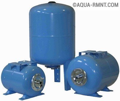
The volume of the expansion tank for water supply can be different, it is selected based on the needs of users. If you subsequently need more volume, you can install an additional device
Features of self-installation
All expansion tanks can be divided into two groups, determined by the method of connection. There are vertical and horizontal models. There are no special differences between them. When choosing, they are guided by the parameters of the room where the equipment will be placed. During the installation, you should follow these recommendations:
- The expansion tank is installed in such a way that it can be easily accessed for maintenance.
- It is necessary to provide for the possible subsequent dismantling of the connecting pipeline for the replacement or repair of equipment.
- The diameter of the connected water pipe can not be less than the diameter of the branch pipe.
- It is necessary to ground the device, so electrolytic corrosion can be avoided.
The device is mounted on the suction side of the pump. On the line between the pumping equipment and the connection point, all elements that can introduce significant hydraulic resistance into the system must be eliminated. The supply line is connected to the circulation circuit of the entire system.
Dear friends. there is such a thing in our economy as membrane tank. It's the same closed expansion tank. It's the same aqua accumulator. And it is very likely that there are not one of these tanks, but two, or even more. Most likely one such device is in the water supply, and many have it in the heating system. The tank must be under pressure, or, more simply, it must be pumped up. For inflation, an automobile pump is used to pump the tires.
How do we usually pump up our tank? First of all, we drain the water from the system. Then we remove the cap, which closes the air nipple, connect the pump hose to the nipple and start pumping. The air pressure is controlled by a manometer, which is most often connected directly to the pump.
What air pressure should be in the tank without water? On a good tank this should be written. On my written (I have a good tank). The air pressure should be 2 tenths of an atmosphere lower than the pressure of the water pump. Do you know the pressure of the water pump? If you do not know, it means that the water was wasted. This had to be known in advance.
But I'm always too lazy to drain water from the water pipe and especially from heating. A pump can sometimes be needed. What to do? Is it possible to pump the tank if it is under water pressure? I think you can, but very carefully! In order to understand the pressure of the air to pump our tank, we need to get a good idea of how it works from the point of view of physics. Fortunately, the laws are trivial and you will not need any formulas. We will manage words.
Water pressure and air pressure
In this article, I first look at the problem from a theoretical point of view. I do not even take the tank myself, but the ideal model and see what processes take place in it. And only closer to the end of the article I point out, what is the difference between our ideal model and the real tank
This, as they say in Odessa, two big differences. Water is incompressible, therefore, it is impossible to create pressure in the water supply system due to water compression. And at the expense of what it is possible? At the expense of just two things. By stretching the water with everything that can be stretched. For example, pipes or hoses.
Crazy idea!
I think that a flexible garden hose from 25 meters long and more can fully fulfill the role of our tank, which, by the way, does not need to be pumped up. But he will not be able to store water either. Will only protect from water shovels. So the idea is good only for watering the garden, but not for the water supply.
A more working idea is to create water pressure with air. Air, just, is compressed very well and can act simply as a spring. That's why it is used in closed expansion tanks. Let us turn to the following scheme. I pictured an expansion tank on it. But conditionally, so you can understand how it operates from the point of view of the principle, and not the real device. Here everything is very simplified. We have a cylinder in which the piston moves. On one side of the piston is water, with another air. The main physical law that we are interested in is that when the gas volume decreases with constant gas weight and temperature, the pressure increases. The dependence is linear. Decreased the volume 2 times - the pressure increased 2 times.
Perfect Expansion Tank
We have air pressure, but no water is connected

Perfect Expansion Tank
The air pressure is there, there is no water.
Suppose we pumped our tank to the right with air to a pressure of 1 bar on the manometer. In this case, it is quite obvious that the piston under pressure of air will be pressed to the left end of our cylinder. Suppose we put some negligible amount of water on the left. Well 1 gram, or 1 thimble, or 1 cc. never mind. Question. Under what pressure will this drop of water be? Under pressure, 1 atmosphere. In fact, a little more, for this drop has moved our piston to some micron, the volume of gas has decreased and the pressure has increased. But since the amount of water is negligible, then we will not consider the growth of pressure either. What else is important? That we could put this drop in the left part of the tank only using a device (pump), creating a pressure greater than the air pressure, for we act water against the air. In our case, this is more than one bar.
Start filling the tank with water
Perfect Expansion Tank
Left of the water, right air. The water pressure is balanced by air pressure. The pressure of both substances is twice the air pressure in the tank without water
What happens if we fill the tank with half the volume of water? The air volume will be reduced by a factor of 2. There was pressure in an empty tank of 1 bar. In the half-filled water, there were 2 bars. Pressure in the water pipe, too, was 2 bars. Everything is very logical. Can we still drive a quarter of the water tank on the left? Let's take that, yes. We can. In this case, the volume occupied by air will decrease by a factor of 2 and we will get air pressure of 4 atmosphere. The water pressure in the system will also be 4 atmospheres.
To what extent can we compress the air on the right? In an ideal scheme, I think, very much. I guess until the air becomes liquid. In actual conditions, after all, we do not have a piston, but a rubber pear, and I have never seen in the characteristics of real tanks an indication of the maximum volume of water in them (see below for more information). I guess everything is regulated by common sense, namely reasonable limits of switching on and off the pump. And let's finally move from ideal schemes to real issues.

Perfect Expansion Tank
The air is compressed by water. The air pressure is 4 times greater than the pressure of the same air in the same tank without water
What is the difference between an ideal and a real expansion tank?
To many. We do not have a piston. Instead of a piston we have a rubber bag, which under pressure crumples. No means for accurately folding the bag is provided. The bag pokes as it wants. Obviously, it forms all sorts of folds. When water breaks into a bag, it folds. Again this bag has a seam.
Rubber itself is also stretched, which introduces certain non-linearities in the described process.
And in general, all the laws about the dependence of pressure and volume (Boyle Mariotte) were written for ideal gas and ideal conditions. Practically only molecules were considered and that's all. With real gas, especially with air, which is a mixture of gases, everything is more complicated, of course.
In the real system there are accompanying factors. Such as the quality of rubber, the quality of the tank, the tuning of the equipment on which the tank was made, the workers' brigade, which these tanks were making. I am sure that the tanks made by workers from Albania will differ from the tanks made by workers from Serbia. I do not know who will do better - I do not know. But what will differ is quite accurate.
Pump On / Off Pressure
What happens if all the water from the tank goes off and the pump does not turn on? In our tank, pumped up to 1 bar empty, the minimum water pressure is 1 bar. That is, our water flows out, the pressure decreases and after 1 bar should simply collapse to zero. Just because there is no water. It's over. The motor starts to work and the entire system experiences an unforeseen load. Water is fired from the pump, hits the pipes and is extinguished by the membrane of the tank, which takes over the entire impact. It's all not very comfortable and quite dangerous. It's much better if the pump turns on when there is still water in the tank! But not too much. In our case, the pump should turn on when the water pressure is greater than 1 bar. How much more? If much more, we will reduce the amount of accumulated water and increase the frequency of the pump starts (it will often turn on for a shorter time), which is not good. Now we begin to understand why we were advised to pump the tank by 2 tenths of the bar less than the pump start-up pressure. In this case, when the pump is turned on in the tank, there will be a reasonable water level. Reasonable - means the manufacturer justified.
And when do we need to turn off the pump? Obviously, here they will tell me what to include at 1 bar, turn off at 4. Then our tank will accumulate a phenomenal three-quarters of the water volume. But it is inconvenient and uncomfortable from the point of view of "go wash." It's comfortable to turn on three and turn off for four. In the most extreme case, turn on two and turn off for four. Here also we consider. If the pressure difference is only 2 times, then our tank is also capable of using half the volume.
Requirements of manufacturers
Producers of good tanks argue that you should not allow the water in the tank to be more than half. So manufacturers are insured against warranty cases. I personally have a good tank of a well-known manufacturer, bought from a representative and I have tested my tank many times with the above method and nothing has happened to it.
What are the very good expansion tanks in the farm?
I give an abstract example. We have a tank of 100 liters of full capacity. We pump it with one bar. Switching the pump on is set to 3 bar, and off to 4. In this case, the minimum remaining water in the tank will be more than a half-tank (more than 50 liters). Our tank will operate on a range of about 12 liters. That is, the pump turns on every fifteen minutes. I think that the pump will withstand such a rhythm, but we get a super comfortable water pipe, in which hot water in the soul does not "walk" at us due to pressure changes. I mean a fairly common case, when hot water cools down with a decrease in pressure in the water pipe, and then again becomes hotter as the pump works to increase the pressure.
And if we assume that we are standing in the shower with a soapy head and turning off the light. What do we think? With the tank, which is adjusted to almost complete dehumidification, we do not know how much water remains in the tank, even if the tank is a capital tank. It is quite possible to turn off the electricity we found when the tank is completely out! And in my proposed scheme, a non-drying residue of as much as 50 liters. I definitely have enough water to finish washing my head and torso even. Even to think there is nothing! You just need to shout to your wife to bring a candle.
And how, after all, pumping a tank of water?
A warning!!!
Manufacturers of tanks prohibit pumping tanks with water. They argue that such actions can damage the membrane. Perhaps the fact is that the rubber bag does not even look like a piston at all. It can be located in the tank unevenly. It can form some wrinkles, can stretch in some unforeseen way and all that. So all of the below is very dangerous for repetition. If you want, do it at your own risk. Personally, I did this with my tanks more than once (and two or three).
We can have only two tank malfunctions, which are associated with air pressure. If the pressure is too high (the tank is pumped), or a little (the tank was blown away).
If the tank is pumped, then we experience the drop of the water gauge needle to zero, and only then turn on the pump. For example, the pressure of the inclusion of 2 bar, air pressure 3. The arrow goes down to three bars, then falls sharply to zero, the pump turns on.
The tank is underdeveloped. You know, in this case, it should somehow work until it is completely deflated. If the tank is blown away from us, then we get an increase in the remainder of the water in the tank. At the same time, the pump runs for a shorter time. After all, he needs less and less! And, by the way, the time before switching on decreases. As a result, the air pressure in the tank disappears. It is completely filled with water and begins to "flash", that is, feverishly turn on and off.
Thus, in a system under pressure it is not so easy to determine the presence of a problem!
If the tank is pumped, the pressure must be discharged through the nipple. If the tank is undershot, it is necessary to measure how much it accumulates water. Then, knowing the switching pressure and the pump off pressure, you can determine, at least approximately, how much water it should pump in one session.
Not knowing how much water is in the tank, we can not accurately determine the air pressure. We can only act approximately.
If the water pipe is flooded, and the system is difficult to drain, there is nowhere, reluctance, and so on
- Turn it off from the network.
- We connect the air pump to the expansion tank. Better electric. But just not a branch pipe from a powerful compressor!
- What is the water pump shutoff pressure (maximum water pressure)? Suppose 4 atmospheres.
- We pump the water tank with air up to 4 bar. Perhaps if the tank is tied with water, it will take quite a bit of time.
- We merge water into the bucket until the air pressure drops to 3.6 bar.
- Then again we shake and again merge. It is necessary to merge about 15 liters. How merged - installed 3.6 atmospheres and this is finished.
- We check with soapy water or drooling, if there is air coming from the nipple. If it does not, then it's good. If it goes, then let's completely air and change the nipple. Nipple is put exactly the same, as it was! If instead of a short nipple put a long one, you can pierce them a pear. It can be completely pressed with rubber to the nipple. We buy a nipple in the autoshop.
Example
Knowing the pump start-up pressure, the tank volume and the knowledge obtained above in this same article, we can estimate how much water pumps the pump in one cycle of increasing the pressure from minimum to maximum. For example, we have a tank of 60 liters. Switching on pressure 1.5 bar, off 3.6 bar. Suppose that the pressure of the tank without water should be 1.3 bar. The non-drying residue in the tank (the moment the pump is turned on) will be rounded 9 liters. At the moment the pump is turned off, there should be somewhere in the tank 46 liters of water. At one time the pump pumps 37 liters into the tank. In the calculations I had in mind that 1.5 bar differs from 1.3 bar by 0.2 bar, which is 13% (!!!). A 3.6 bar differs from 1.3 bar by 2.3 bars, which is from 1.3 to almost 77%
If the pump often turns on and does not work for long (subjective sensations)
Unfortunately, there is nothing to offer, for we do not know how much water is in the tank. And we'll never know until we completely drain the water. I can offer only one. Pump it and see if it will be better. If it does, then leave it until better times. If the tank is small or tiny, then it is dangerous to estimate, for it is very easy to pump. Here it is necessary to drain the water and check the pressure on an empty tank.
What to do with the tank in the heating?
But for the sake of this, I, honestly, wrote the article. Drain the water pipe - easy and pleasant. Drain heating is a problem. Especially if you consider that the frost in the yard, and after pouring will, as always, problems with air in the pipes.
What are the features of the expansion tank installed in the heating system? Features are! The heating tank may not have a rubber pear. Heating tanks come without flanges. Then instead of a rubber pear in the tank is really a membrane. And it is in the middle. And it stretches. There is an analogy with a pear? It's hard to say, but we will assume that yes.
The maximum pressure in the heating system is tiny. Only one and a half atmosphere. Water in the tank should be placed as much as possible. Thus, the minimum air pressure must also be minimal. In my opinion, the main thing is that it just was. And we must remember that there is always pressure in the heating system with water! Simply because there is a natural difference in heights, and considerable.
Thus, the air pressure in the empty expansion tank heating should be, it seems, somewhere 0.5 bar. Then under the maximum pressure of water the tank will contain three quarters of its volume of water. With a 25-liter tank - 18 liters. And this, it seems, is a super-maximum.
Acting with the tank can be similarly described fully deflated tank from the water supply system.
Checked if there is air in the tank? To do this, clicked on the nail or something suitable on the button nipple. If it does not hiss, then connect the pump and pump the air, while draining the water. We lowered a quarter of the volume of the tank and left under pressure at 1.5 atmospheres. We checked the nipple. Then they let down a little water so that the pressure was not the maximum and that's all. We believe that we are ready.
By the way!
Who read to the end and did not understand, can I pump the expansion tanks under pressure of water, I answer - in theory, no. Practically it is possible, but only very carefully and only in some cases. And thus the safety of the tank is not guaranteed.
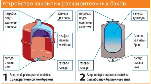
Closed tank
The expansion tank is an auxiliary equipment, but without this device, it is not possible to operate the heating system efficiently. In order for the network to function properly, it is necessary to correctly select and configure the parameters of all its elements. One of the most important indicators in this case is the pressure in the expansion tank.
Why this design?
Before talking about the functions and tuning of the expansion tank, you need to understand the types and operation of this equipment. Why do we need such a design in the heating system? The main task of the device is to compensate for thermal expansion in the network. After all, during heating and cooling, the coolant changes its density and volume.
Note! If this device is not installed in the engineering network, as the water warms up, the water will increase in volume and influence the walls of pipes and radiators. With a strong increase in water pressure, the system can simply break. Installing the expander allows you to save not only the pipeline, but also the boiler. After all, his work is initially calculated for a certain pressure of water in the system.
Expansion devices can vary in volume. When choosing a model that is suitable for a particular network in terms of technical parameters, it must be taken into account that the volume of this element must be at least 10% of the volume of the coolant circulating in the system. To perform this calculation, the volume in the radiators, pipes and boiler is summed. The easiest way to determine the volume is at the time of system injection. It should be remembered that a volume of 10% is a minimum, but it is better to take a model with a small margin.
About expansion tanks for wall-mounted gas boilers is worth mentioning separately. Most modern models with wall mounting have a built-in device mounted on the back or side wall and equipped with a nipple. With the help of a nipple, the pressure is inflated.
The device and the principle of operation
All kinds of expansion tanks have the same device. Inside the metal case there are two sealed compartments. On one side there is a nipple, and on the other - a neck for connection to the pipeline. Inside the case there is a diaphragm. In an empty container, it will occupy most of the volume, while the rest of the space is filled with air.
During the operation of the system, the coolant heats up, increases in volume, and its excess enters the cavity between the body and the diaphragm. When the temperature of the water in the system decreases, its volume decreases, and the injected air squeezes it back into the pipeline.
Installing the Expansion Element
Boiler equipment is designed to work at a certain head of water. This means that in the expansion tank for its normal operation, too, there must be a certain pressure. It is supported by air or nitrogen, which is filled with the body. The air is pumped into the tank at the factory. During installation, make sure that air is not released. Otherwise the device will not be able to function.
The pressure is monitored using a manometer. The running arrow indicates that the air has come out of the expander. In general, this situation is not a serious problem, since air can be pumped through the nipple. The average pressure of water in the tank is 1.5 atm. However, they may not be suitable for a particular system. In this case, the pressure must be adjusted independently.
Normal indices are at 0.2 atm. less than in the system. Strictly do not exceed the pressure in the expansion tank in comparison with this indicator in the network. In such situations, the increased heat carrier can not enter the reservoir. The tank is connected to the pipeline through the connection size.
It is important not only to properly connect the expansion tank, but also to choose the right place for its installation. Despite the fact that modern models can be mounted anywhere, experts advise installing this element of the system on the return between the boiler and the pump.
To ensure maintainability of the structure, a ball valve is installed on the pipe through which the expander capacity is connected. In the event of equipment failure stop valves will remove it without pumping the coolant from the system. During operation of the system, the crane must be open. Otherwise, it will sharply increase pressure, and it will flow at its weakest point.
Installation in the boiler room
AT open systemsoh with natural circulation coolant tanks are installed of other types. Such a tank is an open tank, usually welded from sheet steel. Install it at the highest point of the engineering network.
The principle of operation of such an element is very simple. As the volume increases, fluid is displaced from the pipes, rising along them along with the air. Cooling, the coolant returns to the pipeline under the influence of gravitational forces and natural air pressure.
Why does the pressure drop?
The pressure in the expansion vessel must be constant, but the situation when it falls during the operation of the system is not uncommon.
There are several reasons why pressure can decrease:
- Leakage of coolant. Most often, a similar problem occurs in systems where the coolant is not water, but antifreeze. Such liquids can penetrate into the smallest cracks, causing leakage. In this case, it is necessary to eliminate leaks and fill the tank with air.
- Pressure drop in the boiler. If the indicators are significantly reduced, you need to contact a specialist. If the pressure decreases slightly and is equalized after the start-up of the system, it can be operated, since such failures do not cause harm.
Pressure adjustment
The water pressure in the expansion element of the heating system is a configurable parameter. The setup is simple enough, and all the actions can be done independently.
To configure the necessary settings, you need the following:
Principle of connection
- Make the calculation and determine the required indicators - by 0.2 atm. less than in the system.
- Set these indicators before installing the tank into the system, dropping air or pumping it through the nipple.
- Connect the tank to the pipeline and fill the system with water. This should be done slowly, monitoring the pressure indicators in the pipes and the tank. To pump the coolant should be until the pressure indicators are not equal.
- After this, it is necessary to connect the pumping equipment and continue to pump the coolant. It is necessary to pump the water until the operational pressure calculated before the installation of the network is reached in the tank. This will ensure that there is a reserve volume of water in the body.
- The first activation of the system must be carried out in the maximum temperature mode. Under this condition, the volume of the heat carrier increases by the value of the specific increment. This ensures that a quantity of water equal to its capacity enters the tank. The pressure in the tank rises to the maximum.
Conclusion
The expansion tank is the most important additional element in any heating system. If for open systems with gravitational circulation it is sufficient to install a simple open reservoir at the top point, then for complex systems closed systems The installation of industrial models is required.
These tanks are leakproof. In the production process, air is pumped into the housing, maintaining the pressure necessary for the normal operation of the systems with forced circulation. You can adjust the required pressure indices yourself using a pressure gauge and a conventional automotive compressor.
Related Posts
Applied in cold water supply systems when water is supplied to the house from an external source.
The correct selection, installation and operation of the tanks will provide safe work systems and will reduce the probability of occurrence of emergency situations.
Membrane VALTEC tanks for heating systems
The purpose of the VALTEC expansion tank
The main task of the membrane expansion tank in the heating system is to compensate for the increase in the volume of water due to its temperature expansion.
If there is no capacity in the closed system where excess coolant can flow, even a slight increase in temperature will result in an increase in pressure, which may exceed the maximum permissible value for the elements of the hydraulic system.How the expansion tank VALTEC works
In the expansion diaphragm tank there is a diaphragm that divides it into two parts, one of which contains nitrogen, which is under initial excess pressure, and the other part receives excess coolant from the system.
Initially, the entire volume of the expansion vessel is completely occupied by nitrogen; when the coolant is heated, its volume increases, which leads to a compression of nitrogen. The pressure of the nitrogen pad increases and is equalized with the pressure in the heating system at this static level. When the temperature of the coolant and, accordingly, its volume decreases, the pressure of the nitrogen pad returns the coolant back to the system, preventing the pressure in the system from dropping below the tuning level.
The connection point of the expansion tank VALTEC to the heating systemThe pressure at the point of connection of the membrane tank to the system is always equal to the static pressure at a given point at given temperature parameters.
Thus, the parameters of operation of all other elements of the heating system, the required initial pressure in the expansion tank and the volume of the tank itself depend on the location of the expansion tank. In Fig. 1 shows several options for connecting a membrane tank to a heating system with the following altitude parameters:- exceeding the upper point of the system over the lower (H) - 10 m;
- the heat generator and safety valve are located 2 m above the lower point of the system (h 1);
- the expansion tank is placed 1 m above the point of its connection to the system (h 2);
- the static pressure at the bottom of the system is 15 m of water. Art.
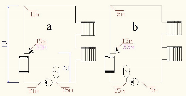
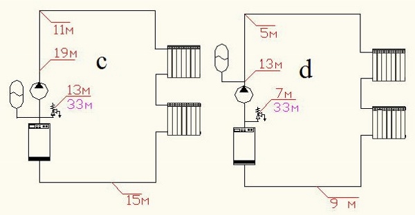
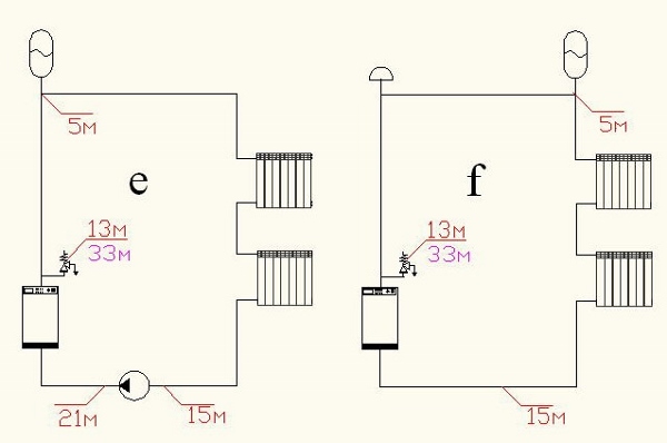
Fig. 1. Options for connecting the membrane tank to the heating system
The outline flags in Fig. 1 designates the calculated values of the working pressure at the characteristic points of each system (in m water).
The value of the safety valve setting is 33 m of water. The pump head - 6 m of water. The system capacity is 200 liters. The difference between the maximum and minimum temperatures of the heat carrier is 80 ºС.
In Table. 1 shows the calculated characteristics of membrane tanks for circuits with their different connections.
Table 1. Calculation data for picture systems 1
Selection of a membrane expansion tank VALTEC
Sufficient volume of the membrane expansion tank is recommended to be determined by the formula:
V b = C · β t / (1 - P a min / P a max), (1)
where C is the total volume of the heat carrier in the heating system, l. Includes volume of water in pipes, boiler, radiators and other elements of the system. This indicator is calculated by the actual capacity of each element of the system; P a min - initial (adjusting) absolute pressure in the expansion tank, bar ; P a max is the maximum absolute pressure possible in the expansion tank, bar.
With a certain error, the value of the volume of the coolant in the system can be selected from Table. 2. At calculations at a stage of the technical and economic substantiation it is supposed to accept specific capacity of system of heating of 15 l / kw.
The values of the coefficient of thermal expansion of the coolant, β t, corresponding to the maximum difference in water temperatures in the nonworking and operating system, are recommended from Table. 3.
The tuning absolute pressure is calculated by the formula:
P a min = P a 0 + P St max - 0,1 · (H B + h 2 + 1), (2)
where P a 0 is the atmospheric pressure, bar; P ст max - static pressure at the low point of the system, bar; Н B - exceeding the point of the tank tie over the lower point of the system, m; h 2 - exceeding the center of the tank above the insertion point, m.
If the tank is located below the insertion point, h 2 is substituted with a minus sign.
Absolute maximum pressure possible in the expansion tank:
P a max = P a 0 + P PK + P st B - P st PK - 0,1 · h 2, (3)
where P PC is the pressure setting of the safety valve, bar; Pst B - static pressure at the level of the safety valve installation, bar; P St PC - static pressure at the level of the tie into the membrane tank system, bar.
Table 2. Estimated volume of coolant in the system
Table 3. The value of the coefficient of thermal expansion of heat carriers β t
| Temperature, ° С | Glycol content,% | |||||||
| 0 | 10 | 20 | 30 | 40 | 50 | 70 | 90 | |
| 0 | 0,0002 | 0,0032 | 0,0064 | 0,0096 | 0,0128 | 0,0160 | 0,0224 | 0,0288 |
| 10 | 0,0004 | 0,0034 | 0,0066 | 0,0098 | 0,0130 | 0,0162 | 0,0226 | 0,0290 |
| 20 | 0,0018 | 0,0048 | 0,0080 | 0,0112 | 0,0144 | 0,0176 | 0,0240 | 0,0304 |
| 30 | 0,0044 | 0,0074 | 0,0106 | 0,0138 | 0,0170 | 0,0202 | 0,0266 | 0,0330 |
| 40 | 0,0079 | 0,0109 | 0,0141 | 0,0173 | 0,0205 | 0,0237 | 0,0301 | 0,0365 |
| 50 | 0,0121 | 0,0151 | 0,0183 | 0,0215 | 0,0247 | 0,0279 | 0,0343 | 0,0407 |
| 60 | 0,0171 | 0,0201 | 0,0232 | 0,0263 | 0,0294 | 0,0325 | 0,0387 | 0,0449 |
| 70 | 0,0228 | 0,0258 | 0,0288 | 0,0318 | 0,0348 | 0,0378 | 0,0438 | 0,0498 |
| 80 | 0,0290 | 0,0320 | 0,0349 | 0,0378 | 0,0407 | 0,0436 | 0,0494 | 0,0552 |
| 90 | 0,0359 | 0,0389 | 0,0417 | 0,0445 | 0,0473 | 0,0501 | 0,0557 | 0,0613 |
| 100 | 0,0435 | 0,0465 | 0,0491 | 0.0517 | 0,0543 | 0,0569 | 0,0621 | 0,0673 |
| 110 | 0,0515 | 0,0545 | 0,0568 | 0,0591 | 0,0614 | 0,0637 | 0,0683 | 0,0729 |
| 120 | 0,0603 | 0,0633 | 0,0653 | 0,0673 | 0,0693 | 0,0713 | 0,0753 | 0,0793 |
As the analysis of formula 1 shows, the best choice of the volume of the expansion diaphragm tank is directly related to the correct setting of the safety valve (according to SP 41-101-95 "Design of heat points" is a mandatory element for the expansionist element). It is usually tuned to a pressure that is 10% higher than the allowable value for the most vulnerable element of the system (taking into account the difference in valve heights and the protected element). Therefore, for heating systems, it is recommended to use valves with the possibility of adjusting the pressure settings. In addition, the valve must necessarily have a device for forced opening ("detonation") for periodic testing of its operability and to avoid sticking of the spool. An example of such a valve is shown in Fig. 3. 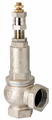 Fig. 3. Safety valve VALTEC VT.1831 with the possibility of adjustment and forced "blasting" Fig. 3. Safety valve VALTEC VT.1831 with the possibility of adjustment and forced "blasting" |
The tuning pressure of the tank should not be less than the hydrostatic pressure at the center of the tank by more than 1 m of water. Art. (0.1 bar). Otherwise, already in the process of filling the system, the useful volume of the tank will be filled with the heat carrier, and with subsequent heating and expansion of the liquid, a smaller volume will be provided than necessary. In other words, if the tuning (factory) pressure in the tank is 1.5 bar, then the system must be filled to the pressure at the center of the tank, which does not exceed 1.6 bar. If the project requires more hydrostatic pressure in the system, then, before installing the tank, it needs to raise the pressure with an air pump.
In two identical systems, differing only in the type of coolant, a larger volume is required in the system where an antifreeze coolant based on glycol (ethylene or propylene glycol) is used, since the expansion coefficient of glycol solutions is slightly higher than that of water.Thus, when changing from a water system to a glycol system, it may be necessary to change the tank to a larger one or to install an additional expansion tank.
A signal to the fact that the system needs a tank of greater capacity is the frequent actuation of the safety valve.
Examples of tying with membrane tanks
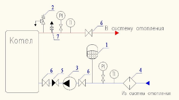
Fig. 4. Installation of the expansion tank in the system with one boiler: 1 - expansion tank; 2 - safety valve; 3 - circulation pump; 4 - the filter; 5 - check valve; 6 - stopcock; 7 - air vent
In this case, the expansometer is located on the return line of the system, which allows it to operate at a lower coolant temperature than if it were installed on the supply line. This solution allows you to extend the life of the device. The connection of the tank to the pump suction connection protects the pump from cavitation.
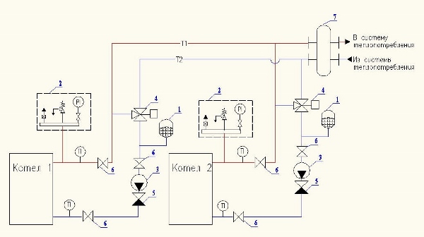
Fig. 5. Installation of expansion tanks in a system with several boilers and automatic limitation of the minimum water temperature in the return pipeline (one tank per boiler is provided): 1 - expansion tank; 2 - safety group (safety valve, manometer, air vent); 3 - circulating pump; 4 - three-way mixing valve; 5 - the non-return valve; 6 - stopcock; 7 - hydraulic arrow
In this scheme, one expansion tank per boiler is provided. The capacity of each of them must be no less than the calculated capacity for the entire system, i.e. if the calculation requires a tank capacity of 80 liters, then this should be the capacity of each of the installed equipment. This is due to the fact that when working at a reduced power, when the burner of one of the boilers turns off, the corresponding circulation pump is also shut off and the closing three-way valve. At the same time, there is no water circulation through the disconnected boiler, and the expansion tank installed on this boiler is isolated from the rest of the system. The remaining expansosom must ensure that the expansion of the coolant is compensated throughout the system. This is also true when using two-way valves, which perform the function of blocking boilers.
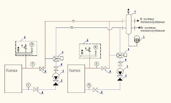
Fig. 6. Installation of the expansion tank in a system with several boilers and automatic limitation of the minimum return water temperature (one expansion tank for the whole system): 1 - expansion tank; 2 - safety group (safety valve, manometer, air vent); 3 - circulating pump; 4 - three-way mixing valve; 5 - the return valve; 6 - stopcock; 7 - hydraulic arrow
Membrane tanks for domestic hot water systems
The main difference between membrane tanks for water supply is that the water in them should not come into contact with the walls of the housing, as it is permitted in heating systems. Therefore, they always use a chamber type membrane (in the form of a bag). In addition, the material of the membrane of the tanks for water supply is subject to increased requirements for the permissibility of contact with food liquids.
The calculation of the expansion tank for DHW is carried out according to the formula 1. The water volume in the system is calculated taking into account the water contained in the pipelines and the water heater or heat exchanger.
An example of installing a diaphragm tank for DHW is shown in Fig. 7.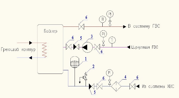
Fig. 7. Installation of the expansion tank in the hot water supply system: 1 - expansion tank; 2 - safety valve; 3 - the pump; 4 - the filter; 5 - the non-return valve; 6 - stopcock
Membrane VALTEC tanks for HDV systems (hydraulic accumulators)
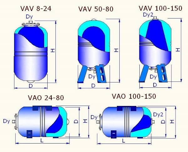
| Make | Volume, l | D, mm | N, mm | L, mm | Dy | Dy2 |
| VAV 8 | 8 | 200 | 333 | 3/4 | ||
| VAV 12 | 12 | 280 | 323 | 3/4 | ||
| VAV 24 | 24 | 280 | 523 | 3/4 | ||
| VAV 50 | 50 | 365 | 683 | 3/4 | ||
| VAV 80 | 80 | 410 | 795 | 3/4 | ||
| VAV 100 | 100 | 495 | 809 | 3/4 | 3 / 4x1 / 2 | |
| VAV 150 | 150 | 495 | 1079 | 3/4 | 3 / 4x1 / 2 | |
| VAO 24 | 24 | 280 | 297 | 523 | 1 | |
| VAO 50 | 50 | 365 | 382 | 595 | 1 | |
| VAO 80 | 80 | 410 | 427 | 728 | 1 | |
| VAO 100 | 100 | 495 | 517 | 730 | 1 | 3 / 4x1 / 2 |
| VAO 150 | 150 | 495 | 517 | 1000 | 1 | 3 / 4x1 / 2 |
Nomenclature and overall dimensions
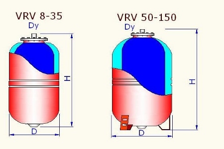
| Make | Volume, l | D, mm | N, mm | Dy |
| VRV 8 | 8 | 200 | 333 | 3/4 |
| VRV 12 | 12 | 280 | 323 | 3/4 |
| VRV 18 | 18 | 280 | 423 | 3/4 |
| VRV 24 | 24 | 280 | 523 | 3/4 |
| VRV 35 | 35 | 365 | 473 | 3/4 |
| VRV 50 | 50 | 365 | 605 | 3/4 |
| VRV 80 | 80 | 410 | 735 | 3/4 |
| VRV 100 | 100 | 495 | 809 | 3/4 |
| VRV 150 | 150 | 495 | 1079 | 3/4 |
Normative requirements for membrane tanks
| Requirement of normative | Standard |
| 4.34. Expansion tanks must be cylindrical; for tanks with an internal diameter of the shell up to 500 mm, flat welded or elliptical bottoms should be taken, and with a diameter of more than 500 mm - elliptical. | SP 41-101-95 |
| 4.35. Expansion tanks must be equipped with safety valves. | |
| 4.47. The safety devices must be designed and adjusted so that the pressure in the protected element does not exceed the calculated pressure by more than 10%, and at a design pressure of up to 0.5 MPa - no more than 0.05 MPa. Calculation of the capacity of safety devices should be carried out in accordance with GOST 24570. | |
| 7.2.6.1. To compensate for thermal expansion of the coolant in independent heating systems, expansion tanks should be provided. | SP 31-106-2002 |
| 7.2.6.2. In the water heating system with the artificial motivation of the coolant circulation, open or closed expansion tanks located in the heat generator room can be used. It is recommended to use expansion tanks of diaphragm type with thermal insulation. | |
| 7.2.6.3. The required capacity of the tank is set depending on the volume of the heating medium in the heating system. | |
| 5.19. To receive excess water in the system when it is heated and to make up the heating system in the presence of leaks in autonomous boiler houses, it is recommended to provide expansion tanks of diaphragm type. | SP 41-104-2000 |
| 3.4. It is not allowed to use metal-polymer pipes for expansion, safety, overflow, signal pipelines. | SP 41-102-98 |
| 13.14. Water and hydropneumatic tanks drinking water, as well as storage tanks should be made of metal with external and internal corrosion protection; while for internal corrosion protection, materials approved by the Glavsanepidnadzor of Russia should be used. For storage tanks of hot water systems, thermal insulation should be provided by calculation. | SNiP 2.04.01-85 * |
| 13.17. Hydropneumatic tanks must be equipped with a supply, discharge and discharge pipes, as well as safety valves, manometers, level sensors and devices for replenishment and regulation of air reserves. | |
| 13.10. A stock of water in storage tanks, arranged in domestic buildings and premises industrial enterprises, should be determined depending on the time of their filling during the shift, taken with the number of shower screens: 10-20 - 2 hours; 21-30 - 3 hours; 31 and more - 4 hours. |