Standard supply of heat carrier from thermal power plants by temperature. Calculation of the temperature schedule and the mode of heating
Temperature chart heating systems of 95 -70 degrees Celsius - this is the most popular temperature chart. By and large, it is safe to say that all central heating systems operate in this mode. The only exceptions are buildings with independent heating.
But in autonomous systems there may be exceptions when using condensing boilers.
When using boilers operating on the condensation principle, the temperature schedules of heating tend to be lower.
The use of condensing boilers
For example, at maximum load for a condensing boiler, there will be a mode of 35-15 degrees. This results from the fact that the copper gets heat from the leaving gases. In a word, with other parameters, for example, the same 90-70, it will not be able to work effectively.
Distinctive properties of condensing boilers are:
- high efficiency;
- economy;
- optimum efficiency with minimum load;
- quality materials;
- high price.
You have heard many times that the efficiency of a condensing boiler is about 108%. Indeed, the instruction says the same thing.

But how can this be, because we have been taught from the school desk that more than 100% does not happen.
- The thing is that when calculating the efficiency of conventional boilers, the maximum is exactly 100%.
But ordinary ones simply throw flue gases into the atmosphere, and condensation gases dispose of part of the outgoing heat. The latter will go on heating in the future. - The heat that will be recycled and used in the second round and added to the efficiency of the boiler. Typically, a condensing boiler disposes of up to 15% of flue gases, it is this figure that is coordinated with the efficiency of the boiler (approximately 93%). The result is the number of 108%.
- Undoubtedly, the utilization of heat is a necessary thing, but the boiler itself for such work costs a lot of money..
The high price of the boiler is due to stainless heat-exchange equipment, which utilizes heat on the last chimney path. - If instead of such stainless steel equipment to put the usual iron, then it will become unusable after a very short period of time. Since the moisture contained in the flue gases has aggressive properties.
- The main feature of condensing boilers is that they achieve maximum efficiency with minimum loads.
Conventional boilers () on the contrary reach the peak of economy at maximum load. - The beauty of this useful property is that during all heating period, the load on the heating is not all the time maximum.
From the power of 5-6 days, an ordinary boiler runs at maximum. Therefore, a conventional boiler cannot compare in performance with a condensing boiler, which has maximum performance with minimum loads.
You can see a photo of such a boiler a little higher, and the video with its work can be easily found on the Internet.

Conventional heating system
It is safe to say that the temperature schedule of heating 95 - 70 is most in demand.
This is explained by the fact that all the houses that receive heat supply from central heat sources are designed for work in this mode. And we have more than 90% of such houses.

The principle of operation of such heat generation occurs in several stages:
- heat source (district boiler house), produces water heating;
- heated water through the main and distribution networks moves to consumers;
- in the consumer’s house, most often in the basement, hot water is mixed with the water from the heating system, the so-called return, the temperature of which is not more than 70 degrees, through the elevator assembly, and then heats up to a temperature of 95 degrees;
- further heated water (the one that is 95 degrees) passes through the heating devices of the heating system, heats the rooms and returns to the elevator again.
Council If you have a cooperative house or a society of co-owners of houses, then you can set up an elevator with your own hands, but this requires strict adherence to the instructions and the correct calculation of the throttle plate.
Poor heating system
Very often we hear that the heating of people does not work well and is cold in the rooms.
The explanation for this may be many reasons, the most common are:
- the temperature chart of the heating system is not followed; the elevator may have been incorrectly calculated;
- the house heating system is heavily polluted, which greatly impairs the passage of water through the risers;
- bricked up radiators;
- unauthorized change of the heating system;
- poor insulation of walls and windows.
Often a common mistake is an incorrectly calculated elevator nozzle. As a result, the function of mixing water and the work of the entire elevator as a whole is disrupted.
This could happen for several reasons:
- negligence and lack of knowledge of operating personnel;
- miscalculations in the technical department.
For many years of operation of heating systems, people rarely think about the need to clean their heat supply systems. By and large, this applies to buildings that were built during the Soviet era.
All heating systems must undergo a hydropneumatic flushing before each heating season. But this is observed only on paper, since the LCDs and other organizations perform these works only on paper.
As a result, the walls of the risers become clogged, and the latter become smaller in diameter, which violates the hydraulics of the entire heating system as a whole. The amount of transmitted heat decreases, that is, someone simply lacks it.
You can do the hydropneumatic blowing with your own hands, it is enough to have a compressor and a desire.
The same applies to the cleaning of radiators. For many years of operation, radiators inside accumulate a lot of dirt, silt and other defects. Periodically, at least once every three years, they should be disconnected and rinsed.
Dirty radiators greatly impair the heat output in your room.
The most common moment is the unauthorized change and redevelopment of heating systems. When replacing old metal pipes with metal ones, diameters are not respected. And even different bends are added at all, which increases local resistance and degrades the quality of heating.

Very often, with such unauthorized reconstruction, the number of radiator sections also changes. And really, why not put yourself more sections? But in the end, your housemate, who lives after you, will receive less heat he needs for heating. And the last neighbor who will receive less warmth the most will suffer the most.
An important role is played by the thermal resistance of walling, windows and doors. As the statistics show, up to 60% of heat can go through them.
Elevator hub
As we already said above, all water-jet elevators are intended for mixing water from the heating supply network into the return flow of the heating system. This process creates a circulation system and pressure.
As for the material used for their manufacture, they use cast iron and steel.
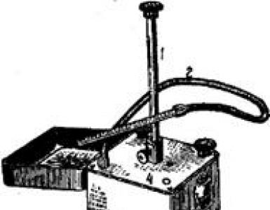
Consider the principle of the elevator on the photo below.

Through pipe 1, the water from the heating network passes through the ejector nozzle and with great speed enters the mixing chamber 3. There, water from the return heating system of the building is mixed with it, the latter is fed through pipe 5.
The water that came out as a result is sent to the heating system through a diffuser 4.
In order for the elevator to function properly, it is necessary that its mouth is correctly selected. To do this, calculations are performed using the formula below:
Where ΔРнас - calculated circulating pressure in the heating system, Pa;
Gcm- water consumption in the heating system kg / h.
For your information!
However, for such a calculation will need a heating scheme of the building.

What laws are subject to changes in the temperature of the coolant in central heating systems? What is it - the temperature schedule of the heating system 95-70? How to bring the heating parameters in line with the schedule? Let's try to answer these questions.
What it is
Let's start with a couple of abstract theses.
- With changing weather conditions, the heat loss of any building changes after them.. In freezing in order to maintain a constant temperature in the apartment, much more thermal energy is required than in warm weather.
Specify: the cost of heat is determined not by the absolute value of the air temperature on the street, but by the delta between the street and the interior.
So, at + 25C in the apartment and -20 in the yard, the heat costs will be exactly the same as at +18 and -27, respectively.
- Heat flow from heating device at a constant temperature of the coolant will also be constant.
A drop in room temperature will slightly increase it (again, by increasing the delta between the coolant and the air in the room); However, this increase will be categorically insufficient to compensate for the increased heat loss through the building envelope. Just because the lower threshold of temperature in the apartment is limited by current SNiP to 18-22 degrees.
The obvious solution to the problem of increasing losses is to increase the temperature of the coolant.
Obviously, its growth should be proportional to the decrease in street temperature: the colder it is outside the window, the greater the heat loss will have to be compensated. Which, in fact, brings us to the idea of creating a specific table for matching both values.
So, the graph of the temperature of the heating system is a description of the dependence of the temperature of the supply and return pipelines on the current weather outside.
How things are arranged
There are two different types of charts:
- For heat networks.
- For in-house heating system.

To clarify the difference between these concepts, it is probably worth starting with a brief insight into how central heating works.
CHP - heat networks
The function of this bundle is to heat the coolant and deliver it to the end user. The length of heating mains is usually measured in kilometers, the total surface area is in the thousands and thousands square meters. Despite the measures for thermal insulation of pipes, heat loss is inevitable: having gone from the CHP or boiler room to the border of the house, technical water will have time to cool down partially.
Hence the conclusion: in order for it to reach the consumer, while maintaining an acceptable temperature, the supply of the heating main at the exit from the CHP plant should be as hot as possible. The limiting factor is the boiling point; however, with increasing pressure, it shifts towards higher temperatures:
| Pressure, atmosphere | Boiling point, degrees Celsius |
| 1 | 100 |
| 1,5 | 110 |
| 2 | 119 |
| 2,5 | 127 |
| 3 | 132 |
| 4 | 142 |
| 5 | 151 |
| 6 | 158 |
| 7 | 164 |
| 8 | 169 |
Typical pressure in the supply pipe of the heating main is 7-8 atmospheres. Such a value, even taking into account pressure losses during transportation, allows the heating system to be launched in houses up to 16 floors without additional pumps. However, it is safe for highways, risers and connections, hose mixers and other elements of heating and hot water systems.

With some margin, the upper limit of the flow temperature is assumed to be 150 degrees. The most typical temperature graphs of heating for heating mains lie in the range of 150/70 - 105/70 (flow and return route temperatures).
House
There are a number of additional limiting factors in the house heating system.
- The maximum temperature of the heat carrier in it cannot exceed 95 C for two-pipe and 105 C for.
By the way: in preschool educational institutions the restriction is much more severe - 37 C.
The cost of reducing the supply temperature is an increase in the number of radiator sections: in the northern regions of the country, the premises of groups in kindergartens are literally girded by them.

- Delta temperatures between pipelines and return pipelines should be as small as possible for obvious reasons, otherwise the temperature of the batteries in the building will vary greatly. This implies fast circulation of the coolant.
However, too rapid circulation through home system heating will lead to the fact that the return water will return to the highway with excessive heat, which is unacceptable due to a number of technical limitations in the operation of CHP.
The problem is solved by installing one or more elevator nodes in each house, in which a return line is mixed with a stream of water from the supply pipe. The resulting mixture, in fact, ensures the rapid circulation of a large volume of coolant without overheating the return pipeline route.

For in-house networks, a separate temperature schedule is set based on the elevator operation scheme. For two-pipe circuits, a typical temperature graph of heating is 95-70, for one-pipe circuits (which, however, is rare apartment buildings) — 105-70.
Climatic zones
The main factor that determines the scheduling algorithm is the estimated winter temperature. The coolant temperature table should be compiled in such a way that the maximum values (95/70 and 105/70) at the peak of the frost provide the corresponding SNiP temperature in the residential premises.
Let us give an example of the intra-house schedule for the following conditions:
- Heating devices - radiators with coolant flow from bottom to top.
- Heating - two-pipe, with.

- Design temperature of outdoor air is -15 C.
| Outdoor temperature, C | Giving, With | Return, With |
| +10 | 30 | 25 |
| +5 | 44 | 37 |
| 0 | 57 | 46 |
| -5 | 70 | 54 |
| -10 | 83 | 62 |
| -15 | 95 | 70 |
Nuance: when determining the parameters of the route and the in-house heating system, the average daily temperature is taken.
If at night it will be -15, and in the daytime -5, -10C appears as the outside temperature.
And here are some values of estimated winter temperatures for Russian cities.
| City | Design temperature, С |
| Arkhangelsk | -18 |
| Belgorod | -13 |
| Volgograd | -17 |
| Verkhoyansk | -53 |
| Irkutsk | -26 |
| Krasnodar | -7 |
| Moscow | -15 |
| Novosibirsk | -24 |
| Rostov-on-Don | -11 |
| Sochi | +1 |
| Tyumen | -22 |
| Khabarovsk | -27 |
| Yakutsk | -48 |

In the photo - winter in Verkhoyansk.
Adjustment
If the management of the CHP and heat networks is responsible for the parameters of the route, then the responsibility for the parameters of the house network is assigned to the residents. A very typical situation is when with complaints of residents about the cold in the apartments, measurements show deviations from the schedule in the downside. Slightly less often it happens that the measurements in the wells of the heat engines show an elevated return temperature from the house.
How to bring the heating parameters in accordance with the schedule?
Nozzle drilling
When the temperature of the mixture and return temperature is too low, the obvious solution is to increase the diameter of the elevator nozzle. How it's done?
Instructions - at the service of the reader.
- Overlap all valves or valves in the elevator assembly (inlet, house and DHW).
- The elevator is being dismantled.
- The nozzle is removed and reamed by 0.5-1 mm.
- The elevator is assembled and started with air bleeding in the reverse order.
Tip: instead of paronitovye gaskets on the flanges can be put rubber, cut to the size of the flange of the car chamber.

The alternative is to install an elevator with an adjustable nozzle.
Muffling choke
In a critical situation (strong cold and freezing apartments) the nozzle can be completely removed. So that the aspirator does not become a bridge, it is jammed with a pancake of steel sheet with a thickness of at least a millimeter.

Warning: this is an emergency measure that is used in extreme cases, since in this case the temperature of radiators in the house can reach 120-130 degrees.
Differential adjustment
At elevated temperatures as a temporary measure until the end of the heating season, it is practiced to adjust the differential on the elevator with a valve.
- DHW switches to supply line.
- A pressure gauge is installed on the return pipe.
- The inlet valve on the return pipeline closes completely and then gradually opens with pressure control on the pressure gauge. If you just cover the valve, the drawdown of the cheeks on the rod can stop and thaw the contour. The drop is reduced by increasing the pressure at the return flow of 0.2 atmosphere per day with daily temperature control.

Conclusion
Each heating system has certain characteristics. These include power, heat transfer and temperature condition work. They determine the effectiveness of work, directly affecting the comfort of living in the house. How to choose the temperature schedule and heating mode, its calculation?
Drawing up a temperature graph
The temperature schedule of the heating system is calculated by several parameters. Not only the degree of space heating, but also the coolant flow depends on the selected mode. This also affects the current costs of heating maintenance.
The plot of the temperature regime of heating depends on several parameters. The main one is the level of heating water in the highways. It, in turn, consists of the following characteristics:
- The temperature in the supply and return pipe. Measurements are carried out in the corresponding pipes of the boiler;
- Characteristics of the degree of heating of air in the room and on the street.
Correct calculation of the temperature graph of heating begins with the calculation of the difference between the temperature hot water in the direct and giving branch pipe. This value has the following designation:
∆T = Tvh-Tob
Where Twi - water temperature in the supply line, To - the degree of heating of water in return pipe.
To increase the heat transfer of the heating system, it is necessary to increase the first value. To reduce coolant flow ∆t should be minimal. This is the main difficulty, since the temperature schedule of the boiler heating directly depends on external factors - heat losses in the building, air in the street.
To optimize the heating power, it is necessary to make the insulation of the outer walls of the house. This will decrease heat loss and energy consumption.
Calculation of temperature
To determine the optimal temperature conditions, it is necessary to take into account the characteristics of the heating components - radiators and batteries. In particular - the specific power (W / cm ²). This will directly affect the thermal return of heated water to the air in the room.
It is also necessary to make a number of preliminary calculations. This takes into account the characteristics of the house and heating devices:
- Heat transfer resistance coefficient for exterior walls and window structures. It must be at least 3, 35 m² * C / W. Depends on the climatic features of the region;
- Surface power radiators.
The temperature graph of the heating system is directly dependent on these parameters. To calculate the heat loss at home, you need to know the thickness of the exterior walls and the material of the building. The calculation of the surface power of the battery is performed according to the following formula:
Ore = P / Fact
Where R - maximum power, W, Fact - radiator area, cm².

According to the data obtained, the temperature regime for heating and the heat transfer schedule are compiled depending on the temperature outside.
For the timely change of the heating parameters set the temperature regulator of heating. This device is connected to thermometers on the street and indoors. Depending on the current indicators, adjustment of the boiler operation or the volume of coolant inflow into the radiators takes place.
Week programmer is the optimal temperature regulator of heating. With it, you can maximize the automation of the entire system.
Central heating
For district heating, the temperature regime of the heating system depends on the characteristics of the system. Currently, there are several types of coolant parameters supplied to consumers:
- 150 ° C / 70 ° C. To normalize the temperature of the water using the elevator assembly, it is mixed with the cooled stream. In this case, you can make an individual temperature schedule of the heating boiler for a particular house;
- 90 ° C / 70 ° C. Peculiar to small private heating systems, designed for heating several apartment buildings. In this case, you can not install the mixing unit.

The responsibility of utilities includes the calculation of the temperature of the heating schedule and control of its parameters. At the same time, the degree of air heating in residential premises should be at the level of + 22 ° С. For non-residential this indicator is slightly lower - + 16 ° С.
For a centralized system, drawing up the correct temperature schedule for boiler heating is required to ensure the optimum comfortable temperature in the apartments. The main problem is the lack of feedback - it is impossible to adjust the parameters of the coolant depending on the degree of heating of the air in each apartment. That is why a temperature schedule is drawn up for the heating system.
A copy of the heating schedule can be requested at the Management Company. With it, you can control the quality of the supplied services.
Heating system

It is often not necessary to do similar calculations for autonomous heat supply systems of a private house. If indoor and outdoor temperature sensors are provided in the circuit, information about them will be sent to the boiler control unit.
Therefore, in order to reduce the consumption of energy, the low-temperature mode of heating is most often chosen. It is characterized by relatively low water heating (up to + 70 ° С) and a high degree of its circulation. It is necessary for uniform distribution of heat across all heating devices.
To implement such a temperature regime of the heating system, the following conditions will be required:
- Minimal heat loss in the house. However, it is not necessary to forget about the normal ventilation - ventilation equipment is required;
- High thermal efficiency of radiators;
- Installation of automatic temperature controls in the heating.
If there is a need to perform a correct calculation of the system, it is recommended to use special software systems. For self-calculation it is necessary to take into account too many factors. But with their help, you can make approximate temperature graphs of heating modes.
However, it should be borne in mind that an accurate calculation of the temperature schedule of heat supply is done for each system individually. The tables show the recommended values of the degree of heating of the coolant in the flow and return pipe, depending on the temperature outside. When performing calculations, the characteristics of the building and the climatic features of the region were not taken into account. But even so, they can be used as a basis for creating a temperature graph of the heating system.
The maximum load of the system should not affect the quality of the boiler operation. Therefore, it is recommended to purchase it with a power reserve of 15-20%.
Even at the most accurate temperature schedule of the boiler room heating in the course of work, deviations of calculated and actual data will be observed. This is due to the peculiarities of the system operation. What factors can influence the current temperature regime of heat supply?
- Contamination of pipelines and radiators. To avoid this, periodic cleaning of the heating system should be carried out;
- Incorrect operation of regulating and stop valves. Be sure to check the health of all components;
- Violation of the boiler operation mode - sharp temperature fluctuations as a result of pressure.
Maintaining the optimum temperature of the system is possible only with the right choice of its components. To do this, their operational and technical properties should be considered.
Battery heating adjustment can be performed using a thermostat, the principle of which can be found in the video:
Hello, dear readers! For beginnings a bit of theory. How is the heat supply in apartment buildings, high-rise buildings, and accordingly in the apartments? Approximately, I think everyone knows. From the heat source - (CHP, boiler) through the distribution, main heating networks, the heat diverges in the apartments. That is - centralized heat supply, or central heating, in other words. In order for the consumer to be supplied exactly the amount of heat that he needs, there are methods or control modes. There are actually three: qualitative, quantitative, and qualitative - quantitative regulation.Qualitative - regulation by temperature, quantitative - regulation by consumption, and accordingly quantitative quality regulation combines the above two.
Simply put, quality regulation is regulation according to the temperature schedule, that is, depending on the temperature drop outside, the temperature in the heating network rises. Quantitative regulation is the regulation of various regulators, valves, chokes, that is, limiting or increasing the flow depending on the outdoor temperature. Strictly speaking, there is no purely qualitative or quantitative central heating, it is always qualitative and quantitative. However, one of the methods of regulation usually prevails. For example, in the heat supply scheme of most Russian cities, which was inherited from Soviet times, the quality regulation method prevails.
This method required and requires less capital expenditures, it has some other advantages. However, another method is considered to be more promising - in which regulation is carried out by changing the temperature in networks according to the temperature schedule and regulation with the help of regulators and valves in local systems with consumers. In this direction, the heat supply of the “bourgeois”, that is, abroad, developed. Some steps are being taken now and in this direction. However, in most Russian cities, the temperature schedule of heating is still "taxis".
Need to say, in Soviet times , especially in capital construction, at the rate of construction of high-rise buildings that were in the 70-80 years used the so-called heating scheme with an open water catchment in the GVS. This is when water for hot water is taken in thermal point (heat) directly from the heating system. Especially this heat supply scheme was practiced in the Siberian regions. In the western regions of the country, a scheme with closed water distribution for hot water supply is often used (that is, when water supplied for hot water is heated in heating units in heat exchangers with water from the heating circuit). Although in new buildings and in the west of the country, an open heating system was also practiced. So, what am I leading to? Let's look at the standard graphics for open and closed circuit heat supply. This is the temperature graphicsfor open and closed system heat supply .
I could be here of course describe in detail how both of these graphs are calculated. However, I will not do this, you can see mine, where the calculation of the temperature graph of heat supply is given. There is also information about this on the Internet. You can use my program for calculating the temperature graph for a system with an open analysis of hot water (almost all the calculations are automated there, you only need to substitute your source data).
What conclusions can we draw by looking at these graphs? As you can see, there are no fundamental differences between them. Because they are for different cities, it doesn’t matter, only the calculated heating temperatures are minus 43 ° C (Bratsk) and minus 26 ° C (for Moscow), and the break point at different outdoor temperatures. The essence of this does not change.
Note that the line graph of temperatures in the heating network, depending on the outdoor temperature goes to a certain point in the form oblique lines, then from this point (the break point - as it is called in the heating engineer) is already horizontally to the temperature of the beginning of the schedule +8 ° С (temperature of the beginning of the heating season). This is the so-called "shelf" of the temperature graph. And the difference in the two graphs is only that for a closed system the horizontal line (shelf) passes when 70 ° Cand for open system at 65 ° C. What is this horizontal line, what is the kink of the graph, what is it for?The fact is that according to SNiP 2.04.01-85 * "INNER WATER SUPPLY AND DRAINAGE OF BUILDINGS", namely p.2.2. The temperature of the hot water in the field of water pumping should include:
a) not lower than 60 ° С -for systems of centralized hot water supply, connected to open heating systems; b) not lower than 50 ° С -for systemscentralized hot water supply, connected to closed heating systems; Accordingly, for an open system, the schedule is “cut off” at 65 ° C.at the heat source (CHP, boiler room), and in residential buildings there is just water comes withtemperature 63-60 FROM. For closed system on heat source supported 70° C (in order to ensure the normal difference between the heating and the heated medium in the heat exchangers in the heating units of residential buildings). And after the heat exchangers water goes already to the consumer with a temperature not lower than that of SNiP. If it were not for this cut-off on the DHW, the schedule would continue along an oblique line to the very beginning, that is, until +8 FROM, (and at this temperature begins heating season). This so-called temperature chart for heating load. And on this very horizontal "shelf "graphics should be a change of regulation from qualitative to quantitative (automatic regulators, valves), or, in the old manner, the regulation of gaps. Regulation gaps - this is when gate valves at the entrance to the heating station it is periodically completely closed, then opened again. Usually this is done manually. Does this regulation really happen? Yes, some where. Where in ITP (heating units), we installed either electronic weather-dependent elevators with an adjustable nozzle, or, even better, automatically controlled two or three-way valves. However, I think that such modernization has not yet reached more than half of the housing stock.And what happens in such houses from the breakpoint of the temperature graph to the beginning of the graph +8 FROM ? And there is a so-called "pane control". That is, overheating, which inevitably arises, and this is the autumn-spring period, usually it is September-October (the beginning of the heating season), and April-May (the end of the heating season), depending on the region, the heating season begins and ends everywhere . That is why at home in the fall and spring it is so hot that only an open balcony door or a window leaf helps.
I would be happy to comment on the article.
Category:. Bookmark.
Article Navigation
64 comments on " Features of the "national" temperature schedule»
Yes, Yuri, this program for calculating the temperature graph, and the program is my own development. It is absolutely free, and you can transfer and distribute it for free, but not sell, naturally, since it is not for commercial use.
Reply
Reply
Hello, Yuri! T1 is the supply, T2 is the return, T3 is the temperature of the water after the elevator, T1 is heating — the supply temperature, if there were no cuttings for hot water, that is, the temperature schedule would be only heating, T2 is heating — everything is the same as the above for T1 heating, only for the return.
Reply
Reply
Yuri, if you have a hot water supply in the house, and it is almost certainly there, then the return flow to thermal node your 9-storey building should comply with T2 on schedule. T1otop and T2 heating are temperatures for a “clean” heating schedule, without cutting into hot water supply.
Reply
Reply
Well, Yuri, you started a good business.
Reply
Reply
Well, in general, Yuri, you understand correctly. Yes, the temperature in the riser on the lower floor of the building, after all radiators, should be approximately equal to T2 on schedule. If, as you write, such a spread is + 50C in the return pipe in the heating station, and + 38 C in any riser on the lower floor of the building, this is not good. This suggests that the riser is unbalanced, but for what reason, it is necessary to find out. Temperature T2 in the riser on different floors of the building should not be strictly the same, if you mean it. Approximately equal to T2 on schedule, it should be on the lowest floor of the building in the normal version.
It is clear, Yuri. If you describe everything this way, then you have in your house a heat distribution system with a heat flow regulator with a two-way valve and a pump in the flow. This is a normal working pattern. In this scheme, the mixing of water occurs through the jumper, and regulation occurs through two-way valve. But any, even the most competent scheme should be properly assembled, configured. It would be nice of course to see the photo. You can reset me on the email address: [email protected]
As for the elevator, then read my article on the website, Yuri, which is called "Automation of ITP". I wrote there about elevator schemes, and about schemes from two, three way valves and the pump, and about their attitude, the vision of these automation schemes.
Reply
Reply
Good afternoon, Yuri! I looked at the pictures, now the picture is clearer, the pump is on your supply, a two-way valve on the return pipe. Normal circuit, working. Yuri, I have clarifying questions. What is the temperature schedule for your home? And what are your complaints about the service organization, I understand that it is not for heating, but for hot water, that is, the temperature of the hot water supply?
Reply
Clear, Yuri. Send the printout to the same email address, I'll take a look. Essentially, while I can say the following. I think it’s almost certain that the DHW comes directly from the return, and you can make a claim on the DHW, since according to the SNiP, the DHW temperature in this case should be no less than 60 C. For heating, you can hardly prove that, if you have an internal temperature in the room plus 20 degrees, then this corresponds to the standard for rooms (not corner ones). The fact is that the temperature graph is calculated at +20 C for your case, this figure is included in the calculation. If at least a degree lower, +19 degrees for example, then it is already possible to make a claim. And Yuri, specify whether your heat point is automated.
Reply
Yuri, about the internal temperature, that is, in the room. If the calculated temperature for heating for a settlement is minus 30 and lower, then the internal temperature is taken 20 C. If the calculated temperature for heating is above minus 30, then yes 18 C is internal temperature. In your case, for Syktyvkar, tr.ot = minus 36 C, draw your own conclusions. I do not remember, unfortunately, immediately look like this, from what document, look on the Internet. With regard to the temperature of hot water, see SNiP 2.04.01-85 *, I mention about it in the article. Yuri, a printout is desirable for any month in the period from November to March.
Reply
Yuri, looked printouts. The temperature schedule for you is most likely 130/70 C. According to the printouts for the winter months there is no under heating, on the contrary, the overheating is small, but within the normal range, five percent. Therefore, Yuri, I do not advise you to start heating up, you will not make any claims on these printouts. It is better to strain the service organization regarding the balancing of the heating pipes, it is quite possible that there is an imbalance between the heating pipes. Well, about hot water - let them put a hot water temperature regulator, and bring tgvs in accordance with the SNiPovskoy. Now, I think, the DHW is connected directly from the return pipe.
Reply
Well, Yuri, let's break down the points. The temperatures t1 and t2 in the printout should be viewed according to the temperature graph, if on the street -15 С, for example, according to the schedule it means t1 = 96.3 C, t2 = 56.6 С (this is for 130/70 С, I I quickly calculated for your case, according to the printout, the numbers closest to such a schedule). 130 degrees according to the schedule 130/70 C should come to your house after serving at a temperature of 36 ° C for heating. Do you often have this temperature in the city in winter? I think 4-5 days from the strength of the year. And practically, this schedule does not raise the temperature to such a temperature, even in cold weather they usually hold 120-125 C. In the project, you have a 150/70 C schedule, but the project is still of Soviet times, and you do not know your current temperature schedule. Most likely, they made a cut of 130 C, that is, actually 130/70 C. Now, about the water with parameters 105/70, these are water parameters after mixing, you have to mix through a jumper, a pump and a two-way valve, and they are not in vain in the heating unit. I have a separate article about the DHW temperature regulator on the website, that's what I’m talking about, I wrote everything there in detail about the DHW RT. Increasing radiator sections will help you personally, yes, but it will add imbalance in the riser and discomfort to your neighbors.
Reply
Reply
Alexey, I have an article on the site: "Internal heating systems." In it, I consider the types of misalignment of internal heating systems, read.
Reply
Good luck, Yuri! You started a good thing, you need to come up with the mind.
Reply
Hello Sergey! The temperature graph is calculated on the calculated temperature of heating for the settlement tro, which, as you rightly wrote, is taken from table 1, column 5 of the JV "Construction climatology". For Novosibirsk and some cities in the region, the calculated heating temperature is Tpro -39 C. And this is absolutely correct. It is this figure from the "Building Climatology" is taken to calculate the temperature graph. The availability of 0.92 indicates that only 8% of the time, a deviation is possible towards a decrease in the air temperature from the calculated air temperature for heating tro.
Reply
Hello, Alexey! I didn’t have the temperature chart for a closed system at hand, and I took it from the Internet. Here, a special case of the graph is the temperature graph for a closed system when regulating the supply of network water to the heat exchanger with gaps, otherwise, with intermittent regulation. I will express my personal opinion, as a practice, about the temperature in the return line from the break point to the temperature of + 8C (“shelf” of the temperature graph). The fact is that in this range of modes as such there is not yet, and therefore (I will express a seditious thought), even if the return flow in this range is in the form of a straight line, that’s okay. Especially, if the "shelf" is short. But it is more correct to consider the temperature schedule according to the calculation formulas, as it is written in all heat supply textbooks. how to do it, I have a free program in Exel format on the “Download” page, and a separate article on the site.
Reply
Reply
Thank you for your sincere and good words, Alexey!
Reply
Hello, Eugene! The heat supply organization can change the temperature schedule, in accordance with the technical and economic calculations. But the essence of the matter does not change from a change in the temperature schedule - the temperature tvn inside the rooms is +18 C or +20 C they must withstand in any case. The temperature tvn inside the premises is included in the calculation of the temperature graph. Regulatory and technical documentation about the internal temperature of the premises can be found and downloaded on the Internet for free access. Probably, there is a point about the internal temperature in the premises and in the heat supply contract.
Reply
Reply
Hello, Eugene! You are right that if you change the temperature schedule, then the control parameters change accordingly. In your situation, the following options are most likely. The first - the schedule was calculated incorrectly. The second is deregulation internal system heating (in the heat point, on the risers) in the building. Rather, the second option. T1, the temperature at the input, you write, corresponds to the temperature schedule. And the temperature in the return line is T2, at the outlet? It may well be that the flow of network water to your home does not correspond to the calculated, that is, understated. What happens in the neighboring houses, in which the same temperature schedule as in your house? It would be nice, Eugene, to know the answers to these questions.
Reply
Eugene, I looked at your materials, temperature charts and technical conditions. Both graphics are calculated correctly, and 95/65 C and 80/65 C. According to the classical formulas and canons. But as I wrote in the previous comment, when the temperature schedule changes, the control parameters also change. In this case, the flow rate of the heating water is necessarily changing. The load on the heating of the building you have Qot = 0.133 Gcal / h. With a 95/65 C plot, the G consumption for heating the building will be G = Q * 1000 / (t1-t2) = 0.133 * 1000 / 95-65 = 4.43 t / h. And with the 80/65 C plot, the G consumption for heating the building will be G = Q * 1000 / (t1-t2) = 0.133 * 1000 / 80-65 = 8.87 tons / h. Therefore, in order for the internal temperature in the building to correspond to the +20 C schedule adopted in the calculation, it is also necessary to increase the consumption per building by a difference of 8.87 - 4.43 = 4.44 t / h. That is, actually twice. Only with such a flow of network water in the building will be +20 C. But whether this was done in fact, whether the flow of water at the heat source increased, at the district’s buildings, whether the new temperature schedule provided 80/65 C, this is another question.
Reply
Hello, Stanislav! Convectors it makes sense to replace radiators with higher heat transfer (aluminum, bimetal). I cannot say anything about the parameters, I need to look at the scheme, and the temperature graph of the system.
Reply
Elena, you need to look at the heat supply contract, and what temperature schedule is indicated there, and you can also take a copy of this temperature schedule at the heat supply organization. The temperature at the consumer must comply with the temperature schedule specified in the heat supply contract.
Reply
Reply
Well, Vladislav, let's take it in order. The temperature schedule for the release of heat is required to give you, it is not a secret behind seven seals. Contact the engineer for the modes in the heat supply organization, or in the VET (production and technical department). In general, the temperature schedule approved for the heating season should hang on a special stand in the heating station along with the ITP scheme, ITP passport, ITP operation manual, etc. If, as you write, the TSO has technical problems, then very often power supply organizations in such situations Introduce adjusted graphics, with cuts. In general, you need a schedule, Vladislav, so that was what to compare with. The pressure drop on the building in front of the elevator (this is important) must be at least 15 mVst (1.5 kgf / cm2) for a 150/70 C chart, for a 130 / 70С chart it can be even smaller - 1.3 kgf / cm2 (elevator will work). Normal differential pressure after the elevator is about the same, if the supply pressure (for example) 4.1 kgf / cm2, then in the return line to the elevator (after the house valve on the return line) there should be 4.0 kgf / cm2. Pressure losses (1 m.st.st.) are spent here to overcome the internal resistance of the heating system of the building. The resistance of the system may be less than 1 m.st.st., but usually, on average, somewhere in the range of 1.0-1.3 m.v.st. It also depends on the height of the building. The more floors in the building, the greater the number of resistance systems. At the TSC, as a rule, there is enough pressure, on the contrary, it is “knocked down” in the ITP with the help of a pressure regulator or a flow regulator or a throttle washer to create the required disposable head (pressure differential) in front of the elevator. About this I wrote above. The expansion of the cone (correctly - nozzles) of the elevator together with the plug of the kneading of the elevator yes, will help to “push” the heating system. The building will "go", but almost certainly there will be overheating on the return line. And naturally, an increase in the diameter of the elevator nozzle and, consequently, the flow rate of network water will affect the overall hydraulic balance of several buildings. On the neighboring houses, yes, it will, perhaps slightly, but not for the better. In your situation it is necessary to strain the heat supply organization (TCO), and the management company (MC). From the first to require compliance with the parameters of heat supply (temperature, pressure), especially compliance with the temperature schedule. From the second - the correct adjustment of the internal heating systems of buildings. On the input of the gauge may not be (although according to the Rules technical operation thermal power plants it should be, p.9.1.45 PTE TE), and then yes, employees of the Criminal Code and TSO use portable pressure gauges. As for the pressure in the return pipe, if we talk about the building, then yes, the pressure in the return pipe from the house (after the house valve on the return pipe, up to the elevator) is what remains after overcoming the resistance of the house heating system. Pressure in the main distribution networks (those that are underground in the non-passage channels of the heating system) can be maintained by pumping stations.
Reply
Reply
Hello Vladislav! Let's understand further. I don’t know what P3 is in the inspection reports, I don’t use this numbering. P1 is the supply pressure, P2 is the pressure in the return. But judging by the data you give, the pressure drop (available pressure) is not enough for normal operation of the elevator. But this, I think, was understandable from the very beginning. The pressure from the house, as I wrote in the previous comments, after the house valve, this is P2. As for adjusting the elevator assembly, yes, this should be done management Company. The elevator nozzle, of course, is sealed, everything is correctly done. In order to break the seal and engage in adjusting the elevator hub, you need to write an official letter from the management company to the heat supply organization with a notice of the upcoming adjustment. Then, after adjusting, adjusting the elevator unit, invite a representative of the energy supplying organization to seal it. Naturally, in the Criminal Code, they know all this procedure. About a 12-storey building. In general, according to the “Rules for the Technical Operation of Thermal Power Plants”, such houses are allowed to be connected under an independent scheme, Section 9.1.8. Independent scheme is more reliable than dependent. What is an independent and dependent scheme, read on the Internet, Vladislav. As for pressure, 60 m.st. for a 12-storey building, in principle, sufficient pressure.
Reply
Reply
Vladislav, most likely that the TCO does not provide the necessary temperature for the supply of t1. To say exactly this, you need to compare the actual parameters with the temperature schedule, I wrote about this in the comment above. The Criminal Code, yes, can improve the situation by silencing the mix. Then the house will "go." But he does not want to do this. Most likely, due to the fact that they are afraid of overheating on the return line t2. Maybe for some reason I don’t know. As for pressure, 60 m.st.st. Enough to enter the ITP for a 12-storey building at normal conditions (resistance of the internal system of the house does not exceed 1.0 - 1.5 m.v.st). I think that in your house the resistance of the system is just greater than 1.5 m.v.st. The elevator cannot work normally, or as I say, it works "by itself". To muffle the mix is an option, though not the best. The return in such a situation is very likely to overheat, but we must look after the fact. In general, connecting a 12-storey house, and even with such introductory parameters, according to an elevator scheme, is “stress” for the internal heating system of the house. Well, this is my personal opinion.
Thank you, Svetlana!
Reply
Reply
Reply
Reply
Reply
Reply
Reply
Reply
Reply
Reply
Reply
Reply
Reply
Reply
Reply
Reply
Reply
Sample graphics
Centralized heat supply is associated with the standard temperature schedule of the heating system. No one doubts that the temperature of the coolant, and, accordingly, the temperature inside the premises does not change significantly. There are standard values of this indicator, and they range from + 70C to + 95C. Today it is the most demanded temperature condition, which is considered normal. Please note that this indicator refers to the coolant.
But not yet in all cities and towns held central networks heating, so autonomous systems are quite popular here. And in them the temperature graph differs significantly from the first. The emergence of modern condensing boilers and their use in autonomous heating systems has led to an increase in operating efficiency. Therefore, the temperature graphs in this case are reduced.
For example, at temperatures from + 15 ° C to + 35 ° C, the condensing boiler can operate to its maximum. It's all about the design heating devicewhere part of the heat energy is collected from the flue gases. That's the advantage of a condensing boiler. But at a temperature above + 70C it will no longer work effectively. The most interesting thing is that in the instructions for use it is written - condensing boilers have an efficiency higher than 100%. In this case, the work of a conventional boiler is taken as 100%, and since the efficiency of condensation is higher, it is considered that the efficiency also exceeds 100%.
General information on the temperature chart
It is clear that the temperature graph includes the outdoor temperature. And the lower it is, the more heat loss. But what temperature indicator should be taken as a basis for calculation? Everything has long been defined and recorded in the founding documents. The basis is the average temperature for the 5 coldest days of the year. In this case, the coldest winters are chosen - there should be 8 of them, and the period should be 50 years.
Why exactly this approach to the calculation of the average temperature? First, it allows you to prepare for the lowest winter temperatures, which occur only once every few years. Secondly, given this indicator, it is possible to avoid significant investments in the creation of heating systems. If you consider all this in terms of mass development, the amount of savings will be impressive.

Dependence of street temperature on the boiler room
Now, with regard to the temperature inside the heated premises. Of course, first of all it will depend on the temperature of the coolant. But there are a few additional factors:
Modern construction standards have recently changed. Developers are trying to increase the cost of the project due to thermal insulation works, which mainly concern the insulation of facades, basements, foundations, roofs and roofs. Investments in this case are significant, but they are the key to saving on heating, since they entail a reduction in the cost of purchasing fuel. Is this relevant today? Very, therefore, developers and go to increase the cost of construction of houses, knowing that all this will soon pay off a hundredfold.
Radiator temperature
All the indicators discussed above are important. But the main thing is the temperature of the radiators. The optimal temperature schedule of heating in central systems is 70–90 degrees. It is clear that to achieve an optimal indoor mode only by this criterion will be impossible. Moreover, in all rooms the temperature should not be the same, since each room has its own purpose.

Comparative chart
Restrictions on temperature conditions are drawn up for all buildings without exception for this or that purpose. We showed only a small part of the huge list. And the more movements a person performs in a room, the lower the temperature inside it. This is the basis of heat distribution. As a confirmation, in the sports halls, where those present move a lot, it makes no sense to keep the temperature high, so the indicator does not exceed +18 degrees.
And now to the question of what factors determine the temperature inside the batteries? There are only four of them:

Heat loss
But you understand perfectly well that the temperature of the coolant will largely depend on the first criterion, that is, on the outdoor temperature. At zero degrees on the street, the temperature regime must be maintained within 40–45 degrees at the feed and 35–38 at the return pipe - this is for radiators. For convectors, 41–49 and 36–40, respectively.
At twenty degrees of frost, these figures are 67–77 / 53–55 for radiators, and 68–79 / 55–57 for convectors. But at 40 degrees of frost, everything becomes standard, that is, 95/105 at the feed and 70 at the return line.
Some additions

The central boiler rooms, in order to deliver the coolant with a certain temperature to the consumer, also react to the state of the air outside. For example, in a forty-degree frost they produce hot water with an indicator of up to + 140 ° C, which is supplied under pressure. That is why evaporation does not occur. But this temperature is not needed in the apartment. Therefore, an elevator unit is installed in the basements, where water is mixed from the supply pipe with water from the return pipe at home. That is, there is a decrease in temperature to the required.
The most amazing thing is that several organizations are responsible for the whole route, each of which has its own functions. For example, CHP is responsible only for the supply of hot water and the temperature of the coolant in certain conditions. Communal services are responsible for the qualitative maintenance of the heating main, as well as for its thermal insulation. heating network (CCC). But for setting up and maintaining the elevator assembly - housing office. Therefore, when solving a specific problem, it is necessary to know where to turn. But there is one nuance in this division - the size of the nozzle on the elevator establishes the housing office, and this figure is consistent with the CCC. Without their permission to change the diameter is prohibited.
And the last. In the apartment the builders install batteries according to the norms and rules of SNiPs and GOSTs. If you yourself change radiators, piping and valves, then you take full responsibility for the normal temperature conditions. After that, you shouldn't complain that something is wrong with you.

Cranes and adapters
Now a few words about the jumpers that are installed in all apartments. With their help, the question of the work of the heating system at home, even if your radiator has ceased to pass the coolant, is solved. Recently it has been noticed that the builders stopped putting shut-off valves or chokes on the lintels, which is not very good.
Therefore advice! Install 3 shut-off valves in the radiator unit at once - one at the entrance, one at the exit and one at the jumper. With three taps you will be very easy to control the temperature in the room, closing or opening one or the other.
The most amazing thing is that solving a big problem depends on inexpensive materials - these are ordinary ball valves or valves. The only thing you need to pay attention to is the amount of opening. At the entrance you need to open the tap quite a bit, and at the exit and the jumper - completely. So you instantly achieve that the temperature in the radiator, and hence in the room will go down.
Warm floor

Laying pipes on the substrate
This system is becoming increasingly popular today only because it falls into the low-temperature category. For warm floors do not need to heat the coolant to high temperatures. It is enough that the water warms up to + 40C. So, for such a system suitable coolant from the return line.
The most important thing is that in this situation no one loses. But here it is necessary to take into account the frequency of placement of pipes for underfloor heating. The smaller the distance between the pipes, the better, although there are rules that can in no way be neglected. In addition, the "warm floor" system is not recommended for use in apartments with low ceilings. After all, the reduction of the latter will be at least 20 centimeters.
Conclusion on the topic
As you can see, determining the temperature graphs of heating, it is necessary to take into account a fairly large list of various factors and criteria. And this is not only the design of the building and its elements, but also a lot of little things. In any case, the calculation is based on the temperature. outside air. And it does not really matter what system is used to heat your house or apartment. Much more important is the temperature inside the room.