How will the resistance change if the conductors are heated. The Great Encyclopedia of Oil and Gas
The experience in accordance with the general considerations of § 46 shows that the resistance of the conductor depends also on its temperature.
We wind a few meters of a thin (0.1-0.2 mm diameter) iron wire in the form of a spiral and plug it into a circuit containing a battery of galvanic cells 2 and an ammeter 3 (Figure 81). The resistance of this wire will be chosen so that at room temperature the arrow of the ammeter deviates almost to the whole scale. Having marked the ammeter readings, we will strongly heat the wire with the help of a burner. We will see that as the current is heated, the current in the circuit decreases, and therefore the resistance of the wire increases with heating. This result is obtained not only with iron, but also with all other metals. With increasing temperature, the resistance of metals increases. For some metals, this increase is significant: for pure metals, when heated at 100 ° C, it reaches 40-50%; for alloys, it usually is smaller. There are special alloys, in which the resistance almost does not change with increasing temperature; such as, for example, constantan (from the Latin word constans - constant) and manganin. Constantan is used for the manufacture of some measuring instruments.
Fig. 81. An experiment showing the dependence of the resistance of a wire on temperature. When heated, the resistance of the wire increases: 1 - wire, 2 - battery of electrochemical cells, 3 - ammeter
Otherwise, the resistance of electrolytes changes when heated. We repeat the experiment described above, but we introduce an electrolyte instead of an iron wire (Figure 82). We will see that the ammeter readings increase with the heating of the electrolyte, which means that the resistance of electrolytes decreases with increasing temperature. We note that the resistance of coal and some other materials also decreases with heating.
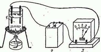
Fig. 82. Experience showing the dependence of the resistance of the electrolyte on temperature. When heated, the resistance of the electrolyte decreases: 1 - electrolyte, 2 - battery galvanic cells, 3 - ammeter
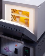
The dependence of the resistance of metals on temperature is used for the device of resistance thermometers. In its simplest form, it is a thin platinum wire wrapped around a mica plate (Figure 83), whose resistance at various temperatures is well known. The resistance thermometer is placed inside the body, the temperature of which is measured (for example, in an oven), and the ends of the winding are connected to the circuit. By measuring the resistance of the winding, you can determine the temperature. Such thermometers are often used to measure very high and very low temperatures, at which mercury thermometers are no longer applicable.
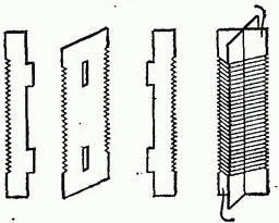
Fig. 83. Resistance thermometer
The increment in the resistance of the conductor when it is heated by 1 ° C, divided by the initial resistance, is called the temperature coefficient of resistance and is usually denoted by a letter. Generally speaking, the temperature coefficient of resistance itself depends on temperature. The value has one meaning, for example, if we increase the temperature from 20 to 21 ° C, and the other when the temperature rises from 200 to 201 ° C. But in many cases the change in a fairly wide temperature range is insignificant, and an average value can be used in this interval. If the resistance of the conductor at a temperature is equal, and at a temperature equal to, the average value
![]() . (48.1)
. (48.1)
Typically, they take the resistance at a temperature of 0 ° C.
Table 3. The average value of the temperature coefficient of resistance of some conductors (in the range from 0 to 100 ° C)
|
Substance |
Substance |
||
|
Tungsten |
|||
|
Constantan |
|||
|
Manganin |
In Table. 3 shows the values for some conductors.
48.1. When the electric bulb is switched on, the current in the circuit at the first moment differs from the current that flows after the light starts to glow. How does the current in the circuit change with a carbon bulb and a light bulb having a metal filament?
48.2. The resistance of the switched off electric bulb with a tungsten filament is 60 Ohm. At full glow, the bulb's resistance increases to 636 ohms. What is the temperature of the heated filament? Use Table. 3.
48.3. The resistance of an electric furnace with a nickel coil in an unheated state is 10 ohms. What will be the resistance of this furnace when the winding is heated to 700 ° C? Use Table. 3.
Page 1
The resistance of metal conductors and their contacts increases with increasing temperature. It should be taken into account that metal conductors and their contacts can have a higher temperature than the electrolyte in the cell, due to additional heating of the metal due to Joule heat. Overheating of metal conductors and their contacts can be especially significant if the cell design does not provide good conditions for cooling the electrolyte of internal conductors and contacts and (by free washing with air) external conductors and contacts.
The resistance of a metallic conductor increases with increasing temperature, since the number of current carriers in a metal practically does not change, and the number of collisions of electrons with ions of the crystal lattice of a metal increases. The resistance of a semiconductor with increasing temperature, on the contrary, decreases, since the number of current carriers sharply increases. Other factors play a less important role here.
The resistance of metal conductors increases with increasing temperature and decreases with its decrease. Each temperature value corresponds to a certain resistance value of the conductor.
The resistance of metallic conductors is due to the collision of free electrons with the ions of the crystal lattice. Free electrons in a conductor make a chaotic motion like molecules of an ideal gas. When the electric field is turned on, chaotic motion of electrons is superimposed by a directed motion-the so-called electron drift in the direction opposite to the field strength vector. During the drift, electrons collide with the ions of the crystal lattice encountered along their path.
The resistance of metal conductors increases with increasing temperature. In semiconductors, the resistance decreases strongly with increasing temperature.
The resistance of metal conductors and their contacts and the loss of voltage in them with increasing temperature increases. And because of their additional heating due to the Joule heat they can have a higher temperature than the electrolyte.
The resistance of metal conductors increases with increasing temperature.
The resistance of the metallic conductor also depends on the temperature: with increasing temperature, the resistance r increases.
In addition to temperature, the resistance of metal conductors of the first class is also affected by other factors, in particular, the field field.
The temperature dependence of the resistance of metallic conductors is widely used in engineering to create resistance thermometers. By placing a known resistance R0 into the furnace and measuring its resistance Rt, it is possible to determine the furnace temperature t according to (15.10). On the other hand, this temperature dependence has a detrimental effect on the operation of precise electrical measuring instruments, changing the resistance of the latter when the external conditions change.
The temperature dependence of the resistance of metallic conductors is widely used in engineering to create resistance thermometers. Rb, it is possible, according to (15.10), to determine the furnace temperature i. On the other hand, this temperature dependence has a detrimental effect on the operation of precise electrical measuring instruments, changing the resistance of the latter when the external conditions change.
The phenomenon of the dependence of the resistance of metal conductors on temperature is widely used in practice. It is based on the principle of the action of devices for measuring temperature, called resistance thermometers. One of the most common is the platinum resistance thermometer, whose thermosensitive element is a thin platinum wire, bifilarly wound on a mica plate.
Basic properties of metal conductors
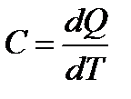
The most important parameters characterizing the properties of conductive materials are: 1) the conductivity γ or its reciprocal value - the resistivity ρ, 2) the temperature coefficient of specific resistance TKρ or α ρ , 3) coefficient of thermal conductivity λ T (previously it was denoted by γ T), 4) the specific heat from; 5) specific heat of fusion r T .
The relationship between the current density δ, (A / m²), and the electric field strength E(W / m), in the metallic conductor, as already shown above, is given by the well-known formula δ = γE,called the differential form of Ohm's law.
For a conductor with resistance R long l and a constant cross-section S, resistivity ρ is calculated by the formula
ρ = RS / l.
For measuring ρ conductor materials it is allowed to use a non-system unit Om · mm² / m. The relationship between the named resistivity units is as follows:
Ohm · mm 2 / m = μOm · m.
Range of resistivity values ρ metal conductors at normal temperatures are rather narrow: from 0.036 for silver and up to about 3.4 μOhm for iron-chromium-aluminum alloys.
The resistance of the conductor depends on the frequency of the current flowing through it. It is known that at high frequencies the current density varies along the conductor cross-section. It is maximal on the surface and decreases as it penetrates into the interior of the conductor. The current is displaced to the surface of the conductor. This phenomenon is called surface effect.It is the stronger the higher the frequency. Since the cross-sectional area through which the current flows decreases, the resistance of the AC wire is greater than its resistance to direct current. For the depth of penetration of current into the conductor at a given frequency take the depth at which the current density decreases in e = 2.72 times. Compared with its value at the surface of the conductor.
Temperature coefficient of resistivity of metals.
The concentration of free electrons n in a metallic conductor, with an increase in temperature, remains practically unchanged, but their average rate of thermal motion increases. The vibrations of the nodes of the crystal lattice also increase. The quantum of elastic vibrations of the medium is commonly called phonon. Small thermal vibrations of the crystal lattice can be considered as a collection of phonons. As the temperature increases, the amplitudes of the thermal vibrations of the atoms increase, i.e. The cross section of the spherical volume, which occupies an oscillating atom, increases.
Thus, with increasing temperature, there are more and more obstacles to the drift of electrons under the action of the electric field. This leads to the fact that the average mean free path of an electron decreases, the mobility of electrons decreases, and as a result, the specific conductivity of metals decreases and the resistivity increases. The change in the resistivity of the conductor when its temperature is changed by 3 K, referred to the value of the resistivity of this conductor at a given temperature, is called the temperature coefficient of resistivity TK ρor . The temperature coefficient of resistivity is measured in K -3. The temperature coefficient of the resistivity of metals is positive. As follows from the above definition, the differential expression for TK ρ has the form:
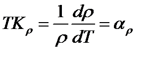 .
.
Heat capacitycharacterizes the ability of a substance to absorb heat Qwhen heated. Heat capacity FROM of any physical body is called a quantity equal to the amount of thermal energy absorbed by this body when it is heated by 3 K without changing its phase state. The heat capacity is measured in J / K. The heat capacity of metallic materials increases with increasing temperature. Therefore, the specific heat FROM determine with an infinitesimal change in its state:
The ratio of the heat capacity FROM to body weight m called specific heat from:
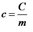 .
.
The specific heat capacity is measured in J / (kg ∙ K). Refractory materials are characterized by low specific heat, while low-melting materials, on the other hand, are characterized by high specific heat.
Thermal conductivity The transfer of the thermal energy Q in a nonuniformly heated medium as a result of thermal motion and the interaction of its constituent particles is called heat transfer. The transfer of heat in any medium or any body occurs from hotter parts to cold ones. As a result of heat transfer, the temperature of the medium or body is equalized. In metals, the transfer of thermal energy is carried out by conduction electrons. The number of free electrons per unit volume of metal is very large. Therefore, as a rule, the thermal conductivity of metals is much greater than the thermal conductivity of dielectrics. The less impurities contain metals, the higher their thermal conductivity. As the impurities increase, their thermal conductivity decreases.
As is known, the heat transfer process is described by Fourier's law:
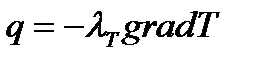 .
.
Here  - the density of the heat flux, i.e., the amount of heat passing along the coordinate x per unit cross-sectional area per unit time, J / m 2 ∙ s,
 - temperature gradient along the coordinate x, К / м,
- coefficient of proportionality, called the coefficient of thermal conductivity (previously designated), W / K ∙ m.
Thus, the term heat conduction corresponds to two concepts: this is the heat transfer process and the proportionality coefficient that characterizes this process.
Temperature and heat of fusion. The heat absorbed by a solid crystalline body upon its transition from one phase to another is called the heat of the phase transition. In particular, the heat absorbed by a solid crystalline solid upon its transition from a solid state to a liquid state is called heat of fusion,and the temperature at which melting occurs (at constant pressure) is called melting point and denote Т ПЛThe amount of heat that must be applied to the unit mass of a solid crystalline body at a temperature Т ПЛfor its transfer to a liquid state, is called specific melting heat rand measured in MJ / kg or in kJ / kg. Depending on the melting point, refractory metals are distinguished having a melting point higher than that of iron, i. E. higher than 3539 ° C and fusible with a melting point of less than 500 ° C. The temperature range from 500 0 C to 3539 ° C refers to the average values of the melting points.
Work function of the electron from the metal.Experience shows that free electrons at ordinary temperatures practically do not leave the metal. This is due to the fact that a retaining electric field is created in the surface layer of the metal. This electric field can be represented as a potential barrier that prevents the electrons from leaving the metal in the surrounding vacuum. Holding a potential barrier is created for two reasons. Firstly, due to the attractive forces from the excess positive charge generated in the metal as a result of the emission of electrons from it, and, secondly, due to the repulsive forces from the side of the electrons that had escaped earlier, which formed an electron cloud near the metal surface. This electron cloud together with the outer layer of positive lattice ions forms a double electric layer whose electric field is similar to the field of a flat capacitor. The thickness of this layer is equal to several interatomic distances (30 -30 -30 -9 m). It does not create an electric field in the outer space, but it creates a potential barrier that prevents the free electrons from leaving the metal.
The specific resistance of metals with heating increases as a result of acceleration of the motion of atoms in the material of the conductor with increasing temperature. The specific resistance of electrolytes and coal under heating, on the other hand, is reduced, because these materials, not counting the acceleration of the motion of atoms and molecules, increase the number of free electrons and ions per unit volume.
Some alloys, which possess a huge resistivity, than the metals that make up them, practically do not change the resistivity with heating (constantan, manganin, etc.). This is implied by the incorrect structure of the alloys and the small mean free time of the electrons.
The value showing the relative increase in resistance when the material is heated by 1 ° (or decreasing when cooled by 1 °) is called temperature coefficient of resistance.
If the temperature coefficient is denoted by α, the resistivity at to = 20 о through ρ o, then when the material is heated to the temperature t1 its resistivity is p1 = ρo + αρ o (t1 -to) = ρo (1 + (α (t1 - to))
and accordingly R1 = Ro (1 + (α (t1 - to))
The temperature coefficient a for copper, aluminum, and tungsten is 0.004 1 / deg. Therefore, when heated at 100 ° their resistance increases by 40%. For iron, α = 0.006 1 / deg, for brass α = 0.002 1 / deg, for fehrrali α = 0.0001 1 / deg, for nichrome α = 0.0002 1 / deg, for constantan α = 0.00001 1 / deg , for manganine, α = 0.00004 1 / deg. Coal and electrolytes have a negative temperature coefficient of resistance. The temperature coefficient for most electrolytes is approximately 0.02 1 / deg.
The property of conductors to change their resistance, depending on the temperature, is used in resistance temperature indicators. Measuring the resistance, the ambient temperature is determined by the calculation method. Constantane, manganine and other alloys having a very small temperature coefficient of resistance are used to produce shunts and additional resistances to measuring devices.
 Example 1. How will the resistance of Ro of a steel wire change when it is heated by 520 °? Temperature coefficient a of iron 0,006 1 / deg. According to the formula, R1 = Ro + Ro α (t1 - to) = Ro + Ro 0,006 (520 - 20) = 4Ro, in other words, the resistance of the steel wire when heated by 520 ° will increase 4 times.
Example 2. Duralumin wires at a temperature of -20 ° have a resistance of 5 ohm. We need to find their resistance at a temperature of 30 °.
R2 = R1-α R1(t2 - t1) = 5 + 0, 004 x 5 (30 - (-20)) = 6 ohms.
The property of materials to change its electronic resistance when heated or cooled is used to measure temperatures. So, thermoresistance, representing a wire made of platinum or pure nickel, fused in quartz, are used to measure temperatures from -200 to + 600 °. Semiconductor thermo-resistors with a huge negative coefficient are used to clearly determine the temperatures in narrower spectra.
 Semiconductor thermal resistors used to measure temperatures are termed thermistors.
Thermistors have the highest negative temperature coefficient of resistance, in other words, when heated, their resistance is reduced. Thermistors are made of oxide (oxidized) semiconductor materials consisting of a consistency of 2 or 3 metal oxides. The most widespread are copper-manganese and cobalt-manganese thermistors. The latter are more sensitive to temperature.
School for an electrician
Page 10 of 21
In electrical installations, products from various materials work together. Widely used: steel structural and electrical, copper, aluminum, bronze, brass, lead, tin, silver, nickel, gold, tungsten, platinum, alloys of various metals, coal, graphite, cable paper, rubber, yarn, polyvinyl chloride, polyethylene, textolite, ebonite, fiber, lubricating and insulating oils, organic and silicate glasses, porcelain, adhesives, varnishes, putties, bitumen, silicon, selenium, germanium, copper-oxide semiconductors, acid and alkaline electrolytes, etc. In a word, it is difficult to find such material that is not used in electrical engineering. And each of the materials possesses only its properties.
The properties of the materials determine the preferential areas of their application, as well as the conditions under which materials can not be used. Rubber, for example, is an excellent insulating material. But if the rubber insulated wires are laid in places where there is oil, the rubber will get wet. In these conditions, plastic insulation is needed. Or another example.
Wires with rubber insulation can not be directly connected to heating devices, as the rubber will burn. Here we need a heat-resistant silicon-organic insulation. Examples can be given without end.
Plants - manufacturers of electrical products proceed from the properties of materials, but sometimes they resort to unacceptable replacements during repairs. The reasons for the substitutions are different. In some cases, they simply do not know that, for example, brass does not always replace red copper - the typical case is considered above, in exercise 20. In other cases, there is no suitable material; for example, a textolite panel is needed for a wet room, and it is replaced by a getinax plate, but the Getinax absorbs moisture, which greatly worsens the insulation of the panel. Thirdly, the cases are tempted by the ease of processing: brass is easy to drill, and red copper is difficult.
In the relevant paragraphs, the influence of various factors on materials and products is considered. And in this section we will focus only on thermal phenomena. But first we emphasize a circumstance that is of fundamental importance: to compare the properties of materials, their parameters are compared under the same conditions. Specific values correspond to such identical conditions, i.e. calculated on a certain unit (lot).
Thus, for example, the conductivity of copper and aluminum is 54 and 32, respectively. Hence, copper is more electrically conductive - in 54: 32 ^ 1.6 times. This follows from the physical sense of the conductivity, which is nothing more than the length of the conductor in meters at a cross section of 1 mm 2 (unit of section) at which its resistance is 1 Ohm (unit of resistance). In our example, in order to get 1 Ohm, one must take either 54 m of copper or 32 m of aluminum wire with a cross section of 1 mm 2.
At a sufficiently high temperature, metals and their alloys melt, and organic substances - coal, paper, etc. - are burned. The melting points of various metals and their alloys are different. For example, the melting points (numbers rounded) of tungsten, steel, nickel, copper, silver, brass, aluminum, zinc, lead, tin are respectively 3410, 1530, 1455.1083.981.900.658.419, 327.232 ° C.
As can be seen from the data given, among the metals there are also highly refractory, for example tungsten, and fusible - lead, tin, zinc. From the tungsten, filaments of incandescent lamps are produced (operating temperature of 2500 ° C) and contacts of a pulse-mode relay, electromagnets with a large inductance commuting with a high frequency. In these cases, the currents are usually small and short-lived, and the contacts heat mainly a spark having a high temperature.
Of fusible metals, mainly lead, fuse-link inserts of inertial fuses; inserts of plate protectors are usually zinc.
Soft solders are: tin (pure tin is used only in special cases) and tin alloys with lead. For example, tin-lead solder GUS-40 contains 40% tin. Important information about soldering is contained in Exercise 23.
Exercise 23. Welding and welding are widely used to connect conductors.
Answer questions: 1. What is the difference between welding and welding? Give examples of the application of soldering and welding. 2. Why is special care required when soldering lead cable couplers? 3. What are the advantages and disadvantages of soft solders and how do they act if their use is unacceptable? 4. What is flux? 5. Why does an overheated soldering iron "not solder"? What do the experienced fitters do in the intervals between soldering?
Answers. 1. Soldering is the joining of parts of an article by means of molten metal solder. When soldering, the parts to be joined do not melt, but only the solder having a lower melting temperature melts. Thus, there is no direct connection between the connected parts. Welding process of joining metals either by their local fusion, or by joint plastic deformation, which results in strong bonds between the atoms of the metals being joined. Typical examples of soldering: the connection of copper conductors to the terminals of the connectors, relay contact plates, semiconductor diodes, and the like. Aluminum is also soldered, but the soldering of aluminum is much more complicated and requires special solder. The aluminum conductors are welded by melting, for example in junction boxes of lighting networks. The joints of buses and branches from them are made by cold welding, i.e. pressure welding.
The melting point of lead is slightly higher than the melting point of the solder, which is why it is easy to overheat and melt the lead sheath of the cable during brazing.
It is easy to sweep with soft tin-Sinic solders, but they are not mechanically strong enough. Consequently, the parts to be joined. if it is possible the occurrence of mechanical loads, it is necessary before brazing to fix (twist the conductors, pass them through the holes in the shanks of the contact springs of the relay, connectors, etc.).
In addition, if it is possible in emergency modes to strongly heat the solder points, the solder can soften and the heated surface oxidize. After cooling the solder, the joint will not work, because in this case there is no flux.
If a high mechanical strength or possibly a strong temperature increase is required, then brazing alloys, for example brass-based, is used. But the temperature of soldering in this case is much higher.
Flux is a substance that dissolves oxides in the molten state, i. E. clears the surface to be welded. Uncleaned surfaces do not weld. When soldering copper, brass, bronze with soft solders, the flux is rosin. When soldering, rosin is not applicable. It is necessary to use hydrochloric acid, etched, zinc. After soldering with acid, the weight of the place where it could get to, should be thoroughly rinsed, otherwise the conductors will corrode.
If the soldering iron is overheated, the rosin begins to burn and, instead of cleaning the surface, it pollutes it. That the soldering iron does not overheat (at the soldering it does not overheat, as the heat leaves on melting of solder), it put on a metal object which allocates excessive heat.
Some metals in the molten state dissolve more refractory metals. Thus, molten tin dissolves copper. This phenomenon is used in the manufacture of copper fuse links fuse. A ball of tin is melted onto a copper wire. When heated to a temperature much lower than the melting point of copper, the ball melts and dissolves copper: the fuse quickly burns out.
Fusing various metals in strictly defined proportions, alloys with the necessary properties are obtained. For example, Nichrome and Fechral can operate at temperatures of the order of 1000 ° C, so they are used in electric heaters.
Reotan and nickel have a high specific resistance, but do not allow high temperatures - these are rheostat alloys.
The main property of manganin - the practical constancy of resistance with changes in temperature - determines the main area of its application. From manganin do shunts for connecting to them ammeters, additional resistance to voltmeters, resistance stores and other exact elements of resistance in electrical measuring equipment.
The temperature coefficient of Invar expansion is approximately 12 times smaller than the temperature coefficient of expansion of steel, so Invar serves as one of the components of terbium-metal (see below, Exercise 29).
Constant n, chromel and alumel materials for thermocouples, compensating wires for them, etc.
In a word, each alloy is designed for a specific purpose and therefore replacement is not always permissible. For example, if the heating spiral is made not from nichrome, but from nickel (its dimensions will be approximately the same), then it will burn out.
When the joints of dissimilar metals (alloys) are heated, the thermal energy directly passes into the electric one: there is a thermal EMF. Other things being equal, the thermoelectric power is proportional to the temperature, on which its measurement is based using thermocouples. The thermocouple is placed in the place of the product where it is required to measure the temperature, and connect it with a millivoltmeter (observing a number of requirements, for example using special compensation wires, etc.). The millivoltmeter scale is graded in degrees Celsius.
Significant thermo-emfs develop thermo-batteries assembled from semiconductors. The thermo battery, put on the glass of a kerosene lamp, gives the power sufficient for the radio receiver to work.
As the temperature rises, the electrical resistance of metals increases, and coal, electrolytes and semiconductor devices decrease. How much resistance changes, can be calculated using the temperature coefficient of resistance. If it is positive, then with increasing temperature the resistance increases, hence, the current decreases, but in the windings of electromagnets, networks, measuring devices, lamps - to varying degrees. Therefore, the effects of varying the current are different. Typical cases are discussed in Exercise 24.
Exercise 24. The current, passing through the metal parts of the electrical installation, heats them: the resistance increases.
Answer the questions and evaluate in which cases the increase in resistance is significant: 1. At a temperature of 10 ° C, the resistance of the winding of the electromagnet R is 500 ohms, and the supply of a copper wire is 1 ohm. The electromagnet was heated to 60 ° C. How will the current in the circuit change? Will the resistance of the supply wire change much? Will the heated electromagnet be "stronger" or "weaker"? 2. All other conditions being equal, the wire is heated by 40 ° C. Will the current in the circuit change from this? Consider two cases: a) the wire is heated by the load current, b) the wire was unloaded, but heated from the fact that it was erroneously laid near the pipeline hot water supply 3. Theater chandeliers with dozens of powerful lamps are switched on for full glow not at once, but gradually, do it "for beauty" or there are more serious reasons? 4. The room temperature in which the voltmeter is installed varies from 10 to 35 ° C , but nevertheless the accuracy of the measurements is preserved in mlemyh within. How can this achieved? Take the temperature coefficients of resistance for copper 0.004, and for manganin 0.000008 degrees. " 5. The temperature of the winding of the electromagnet was indicated above. But it is quite obvious that the outer parts of the winding are cooled better and, consequently, colder than the inner parts of the winding. What is the temperature?
Answers. 1. Temperature coefficient of copper resistance 0.004 deg-1 - Therefore, when heated by 100 ° C, the resistance increases by 40%, and when heated by 60 ° C, it increases by 24%. The current decreases accordingly. The resistance of the wire is 0.2% of the resistance value. It is so small that it should not be taken into account. It is interesting to note that when the current decreases (due to the heating of the winding of the electromagnet), the temperature of the wire decreases (but does not increase) and, consequently, its resistance decreases. But these changes are small and insignificant. Due to the decrease in current, the MDS decreases: the electromagnet becomes "weaker" (see above, Exercise 1).
When heated at 40 ° C, the resistance of the wire increases by 16% and will be 1.16 Ω in our example. But the resistance of the circuit will practically remain the same (501 Ω% 501.16 Ω). For case a) the current heating of the load is normal, for case b) the permissible load on the wire must be significantly reduced.
The working temperature of the filament of the filament lamp is more than 2500 ° C. Therefore, the resistance of the lamp thread prior to its incorporation is about 10 times less than the resistance of the burning lamp and. therefore, the starting current is great and it must be reduced.
The resistance of the voltmeter frame is negligible compared with the additional resistance, since it is made of manganine, and the resistance of manganin is practically stable. If the additional resistance were not manganine but copper, then at the same voltage, the voltmeter readings at 10 ° C would differ from the readings at 35 ° C by 10-12%.
In the condition of the first question, the initial temperature is 10 ° C and the heating at 60 ° C. Consequently, the winding temperature is 10 + 60 = 70 ° C. The temperature of the winding is assumed to be the average temperature, i.e. calculated from the results of resistance measurements.
The dependence of the resistance of metals on temperature is based on its measurement with the help of resistance thermometers.
If the temperature coefficient of resistance is negative, heating leads to an avalanche-like increase in current and must be limited. Indeed, the current heats the conductor (semiconductor) with a negative coefficient of resistance. Resistance decreases, current increases, etc.
On an avalanche-like increase in current when heating semiconductor resistors (thermistors), for example, automatic monitoring of the temperature of bearings is based. Temperature measurement and control based on the dependence of the resistance of conductors and semiconductors on temperature are illustrated in exercises 25 and 26, respectively.
Fig. 9. Measurement of temperature with a thermistor having a positive temperature coefficient of resistance (a) and temperature control by a thermistor with a negative temperature coefficient of resistance 16) - to exercises 25 and 26
Exercise 25. In Fig. 9, a are shown: the power supply source (+, "), measuring instrument I" R - the logometer.
the resistance RK1 and the trimmer resistor R. The thermistor in the corresponding armature is installed in the place where it is required to measure the temperature, for example in an oil tank, and a measuring instrument on the control panel.
Answer the questions: 1. What is in the image of the thermistor RK1: slant and letter 2. What is the electrical quantity proportional to the measured temperature? 3. Why is not just a milliammeter used to measure the current strength, but a logometer? 4. What for in the circuit the tuning resistor is entered?
Answers. 1- Sloping line The standard sign of linear self-regulation emphasizes that the resistance varies in direct proportion to temperature changes, and this process proceeds by itself. without any external influences. The letter indicates the physical value, in our case the temperature, under the influence of which self-regulation takes place.
Proportional to current.
The milliammeter readings depend not only on the resistance (what is required), but also on changes in the voltage of the power supply, and this introduces an error in the measurement. Logometers as well (measure meters) are free from this shortcoming: their indications are practically independent of voltage changes. The fact is that the counteracting moment in the logometer is not created by a spring (as in a milliammeter), but by electric means, i.e. with the help of the second winding in Fig. 9, and it is shown by a green line. Indeed, the lower the voltage, the lower the current passes through the working winding (in Figure 9, and red).
But in the same measure, the current that creates the opposing moment is reduced. When the voltage is increased, the currents in both the working and counter-acting windings are equally increased.
4. Logometers for measuring temperature are graded based on a certain value of the resistance of supply wires. Using the trimmer R, set this value when adjusting.
Exercise 26. In Fig. 9.6. The diagram of the bearing temperature control of a mechanism is shown. Temperature coil semiconductor thermistor (thermistor) RK2 - installed in the bearing shield and connected in series with the coil of the relay K. The stabilized supply voltage from the transformer 75 is selected by means of the taps from the secondary winding so that at a temperature below the set point (for example, below 80 ° C) thermal equilibrium is maintained. This means that the heat released by the current passing through the thermistor is completely discharged by the controlled medium, and the resistance of the thermistor is thousands of ohms. If, however, the temperature rises to the setpoint, the thermal equilibrium is violated, the thermistor temperature increases and its electrical resistance decreases. Reducing the resistance causes a new increase in current and further heating of the thermistor.
The process proceeds in an avalanche manner and quickly causes the relay to trip. Its contacts can be used in any circuits, for example in the signal lamp circuit III., As in our example.
Answer the questions: I. What is indicated by the polyline in the designation of the thermistor RK2 and the inscription t ° 1 2. Explain the purpose of stabilizing the supply voltage. What in the designation of the transformer 7 * 5 indicates stabilization? 3. What is the purpose of the taps from the secondary winding of the transformer and switch 5? 4. Evaluate, raise or lower the set point but temperature if the voltage supplied from the secondary winding of the transformer is increased. 5. It can be seen from the diagram that after the relay K is activated, its contact shorts the thermistor. What would happen to a thermistor in the absence of this contact?
Answers. 1. The broken line denotes non-linear self-regulation: this means that the resistance of the thermistor changes not in proportion to temperature, but is much sharper. The inscription -t indicates the physical value of the temperature, and the minus sign indicates a negative temperature coefficient of resistance. This means that as the temperature rises, the resistance does not increase (as in the resistance thermometer, exercise 25), but decreases.
Without voltage stabilization, its changes would change the temperature setting. Stabilization is indicated by a broken line in the designation of the transformer 75.
The taps serve to set the voltage corresponding to the required setting with the switch 5.
As the voltage is increased, the thermal equilibrium is established at a lower temperature of the controlled medium, hence, the temperature set point is lowered.
burned down.
Temperature changes always lead to a change in the size of the bodies. Thermal expansion is harmful in some cases. Due to the different coefficients of thermal expansion of the materials from which electrical machines are made (steel, copper, insulation), tensile forces arise, resulting in mechanical wear of the insulation. Examples of serious violations in the operation of electrical installations are given in Exercise 27.
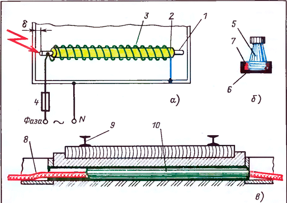
Fig. 10. Thermal expansion can disrupt the operation of electrical installations - to exercise 27
To thermal expansion does not lead to breakdown, take a number of measures, such as tires do not rigidly fix, make them flexible inserts, etc.
Exercise 27. Below are three examples of the failure of the electrical installation due to thermal expansion.
Case A. The failed heating element of the heat exchanger was replaced by a rod 1, on which a nichrome wire 3 was wound over the asbestos insulation 2. The rod was well insulated from the heat exchanger body. One end of the wire was connected to the body of the heat exchanger, and the other to the rod and the power was supplied, as shown in Fig. 10, a. A few minutes after power-on, the fuse 4 blown. Before the next switch-on, a megacomm. Meter measured the insulation resistance of the rod-housing. The insulation was high. At the subsequent inclusion the same thing happened: after a few minutes the fuse blown.
Case B. The porcelain insulator 5 was reinforced with a flange b (Figure 10.6), with cement used as the binder 7 used. In hot weather, a crack formed in the insulator.
Case B. Cable 8 (Figure 10, c), laid under rails 9, was protected from mechanical damage by a piece of pipe 10. In spring, the cable was damaged, and it was in the pipe that was damaged.
Answer the questions: 1. Why did the fuse blow in case A, despite the fact that the insulation measured by the mega-meter before switching on was full? 2. What is the cause of the cracking of the insulator in Case B? 3. What was the damage to the cable? What mistake was made during its installation?
Answers. 1. When you turn on the rod heated up and lengthened. Its left end touched the body of the heat exchanger: a short circuit occurred. While walking behind the megaohmmeter, the rod was slightly cooled and a gap 5 was formed (see Fig. 10a).
The cement expanded when heated. "He could not distribute" a strong cast-iron flange. Therefore, more fragile porcelain cracked.
In the daytime the snow melted, the pipe filled with water. At night, the water froze. And since the volume of ice is more than the volume of water from which ice was formed, the ice squeezed the cable. Installers had to seal the ends of the pipe so that water could not penetrate into the pipe.
Thermal expansion has important useful applications. So, it is on the thermal expansion that expansion thermometers, thermosignals and some versions of direct-acting thermoregulators are based (example given in Exercise 28).
Exercise 28. In Fig. 11, a schematic diagram shows the direct-acting thermostat. As the temperature of the water in the cooling jacket 1 of any mechanism increases, the working fluid enclosed in the thermowell 2 expands and through the connection tube 3 transfers pressure to the rod 6, which in turn presses the valve 7. The valve continues to balance the hydraulic fluid pressure and the spring resistance 8. An increasing flow of water lowers the temperature in the cooling jacket. The pressure of the working fluid in the thermowell decreases, and the spring raises the valve, reducing the flow of water. Thus, the valve "breathes" as it were, passing as much water as necessary to keep its temperature at a given level.
Answer the questions: 1. For what (Fig. 11, o) are the corrugated tubes (bellows) 5 and the handwheel 4 "" 2. On what basis is the thermoregulator called the direct (direct) thermostat?
Answers. 1. Corrugated metal tubes separate air, cooling water and working fluid. They serve as glands, but they are much more perfect due to their complete tightness and mobility without friction.
The flywheel is screwed in or unscrewed by a rod attached to the base of the upper bellows, in other words, stretched or squeezed. This creates the initial pressure of the working fluid, i.e. the desired temperature setpoint is set to the thermostat.
2. The thermometric system directly acts on the valve without any intermediate drives.
Thermal expansion is the basis for the creation of terboymetalla, which is widely used as a temperature sensitive element of automatic switches, thermal relays (for protecting motors from overload), temperature regulators, the simplest time relay used in telephony and often in automation.
![]()
Fig. 11. Thermal expansion has many useful applications - to exercises 28 and 29
The thermobimetal (Fig. 11, d) is made of two welded plates with different temperature expansion coefficients and sufficiently elastic so that there are no residual deformations. One of the metals can be an alloy - Invar, possessing an insignificant coefficient of thermal expansion, the other - bronze. When heated (the temperature in t is greater than the initial temperature c), the plate from the terbiometallic bends to one side, and when it is cooled (c2 less than c), the bending leads to the switching of the contacts, while in others the latch of the mechanism is released. in Exercise 29.
Exercise 29. In Fig. 11,6 the scheme of the simplest bimetallic time relay, the so-called thermogroup, installed on the telephone relay case is given. On the bimetallic plate 13, a heating winding 11 of insulated nichrome wire is wound. When the contact 9 is closed, the current flows into the winding through the adjustable resistor 10. The plate 13 heats up, bends and after a while closes the contact riveted on the plates 12 and 13.
In Fig. 11, c shows a bimetallic thermosignal. The bimetallic plate 17 is fixed to the bracket 16. At normal water temperature, the contacts are open. When the temperature rises, one contact closes, for example, 18 and turns on the green lamp. When the temperature drops, another contact 15 closes and turns on the red lamp.
The circuit diagram of the protective thermal relay is illustrated in Fig. 11, d. The load current / passes through the bimetallic plate 21, the contact 22, the contact bridge 24 and the contact 25. The return spring 26 is compressed (Figure on the left). In the event of significant and prolonged overload, the bimetallic plate bends (figure on the right) and releases the lever 20. The spring 26 lifts the part 23, the lever 20 rotates about the O-axis, the contact opens.
Answer the questions: 1. The time relay in Fig. 11,6 there is a bimetallic plate 14 on which there are no contacts or windings. Is not it an extra detail? 2. In what way is the required time delay specified? Why it should be installed "electrically" (changing the current), and not by bending the spring 12, i.e. increasing the gap between contacts in this way? 3. What is the main disadvantage of a bimetal time relay? 4. In Fig. 11, an inset 19 is shown above the bimetallic plate. Why does it serve and how is its length determined? 5. What is the fundamental advantage of the design, the scheme of which is shown in Fig. 11, d?
Answers. 1. Plate 14 is required to compensate for changes in ambient temperature. The point is that the plate 13 is bent not only under the influence of the heating winding, but also under the influence of the ambient temperature. However, the plate is also bent to the same extent. When the temperature rises, it lifts the plate 12 through the pusher, and, when the temperature is lowered, it leaves: the plate 12 bends downward due to its elasticity. As a result, at any medium temperature, the gap between the plates 12 and 13 remains practically unchanged. In modern thermal relays, in order to protect the motors from overload, temperature compensation is approximately the same way.
Setting the desired setpoint with an adjustable resistor does not disturb the mechanical properties of the relay, and bending the plates, even if it does not lead to permanent deformation, in any case accelerates aging.
The setting depends on changes in the supply voltage of the heating coil.
Without the insert 19, one part of the bimetallic plate 17 would be in a controlled environment - this is good. But another part of it, acting out of the environment, would measure the temperature of the air, and this is bad. The controlled medium should wash the entire bimetallic plate. This condition determines the length of the insert.
The design makes it possible in spite of the slow bending of the bimetallic plate to quickly open the circuit, which is absolutely necessary. If the design does not provide rapid opening, then special measures must be taken to protect the contacts from destruction.
Important note. The location of the sensors for monitoring technological parameters - temperature, level, pressure, flow, speed, displacement, etc., as well as the depth of their immersion in a controlled environment are of paramount importance. So, for example, it is far from indifferent where to install a thermal cylinder of a thermoregulator, a thermocouple, a resistance thermometer. The fact is that the temperatures in the lower and upper parts of the transformer tank are different (the heated oil rises). The temperature of the water near its entry into the cooling jacket and at the outlet is different.
Or another example. If the location of the track or limit switch is not selected, the moving part of the machine will not stop where it should be. In general, all this is much more complicated than it may seem at first glance, and it is often the unsuccessful arrangement of the sensor that causes the unsatisfactory operation of the automation. But in designing these important circumstances are underestimated, and sometimes without the participation of the adjusters simply can not be taken into account.
Particularly sensitive to temperature rises is insulation. Rubber and paper from heating crack and crumble; paper, cardboard, insulating oil, yarn, certain types of plastic, for example non-self-extinguishing polyethylene, can ignite. Organic glass and fiber upon heating soften, lose mechanical strength and are often jarred. The impregnating mass flows out of the capacitors, air bubbles are formed inside it, which is less electrically strong (see below, § 7) than the impregnating mass.
Wax, paraffin, softening paints and varnishes, sometimes used in the repair of electrical equipment, penetrate in the molten form on the surface of the anchors and act like glue. As a result, the relay armature can not release or release with a significant deceleration, violating the operation of the automation.
Overheating of semiconductor devices is extremely dangerous. Semiconductor devices lose their insulating properties as a result of overheating, and if the selenium rectifiers are usually restored after a breakdown, then germanium and silicon hopelessly fail and need to be replaced.
It should be specially emphasized that semiconductor devices have non-linear characteristics; in other words, the conductivity of instruments has a pronounced temperature dependence. This means that even a "not very overheated" product (for example, a computer), if it is designed without proper consideration of the thermal regime, can "suddenly" start to make mistakes. But after enough cooling it works again right until the next overheating.
Permissible temperature, i.e. The temperature at which prolonged operation of insulation is ensured is determined by the class of its heat resistance. The heat insulation classes are designated by the letters Y, A, E, B, F, H and C, which correspond to the permissible temperatures 90,105, 120, 130, 155, 180 and over 180 ° C - all depends on the material. For example, synthetic organic materials (films, fibers, resins, compounds, etc.) belong to class E (120 ° C), to class F (155 ° C) - materials based on mica, asbestos and fiberglass used in combination with synthetic compounds, etc.
Overheating is a deceptive phenomenon. If it is not very large, then its consequences are not immediately obvious, and when they are discovered, it is too late to take any measures - the product is spoiled. In addition, external parts are always heated less than internal ones, especially with intensive ventilation, and this is often misleading. Separate cores of multicore cables can overheat, but for the time being this will also not be noticed.
Many responsible parts of electrical installations not only do not have, but also can not have protection against overheating. At first glance, such a statement is implausible. But consider, 58 for example, an overheating coil of a relay, a contactor, a magnetic starter. While its insulation due to overheating does not completely collapse, the current in the circuit can not increase and, consequently, neither the fuse nor the circuit breaker protect it.
Naturally, the question arises: what is this protection that does not protect? The protection protects, but not the coils, and the electrical installation against short-circuit, and also interrupts the short-circuit current after the coil is burned, thus preventing damage to the electrical installation itself.
Despite the negative influence of heating, it is impossible to avoid the release of heat: once there is a current, then there is heat. However, the release of heat does not mean that the insulation necessarily overheats and can not work long enough and well.
If the thermal (thermal) resistance conditions are met, the insulation is heated within the permissible limits and serves for a guaranteed period. Thermal resistance is expressed in different ways. Let's give some examples.
The voltage is not higher than 110% of the rated voltage. This means that the voltage at the terminals of the product (relay, motor, capacitor, etc.) should not increase by more than 10%. It would seem that this is an unreasonably stringent requirement. However, it is fully justified. Indeed, in a circuit with an active resistance, the current is proportional to the voltage. Hence, an increase in voltage, for example, by 30% causes an increase in current also by 30%. But the amount of heat is proportional to the square of the current, therefore, the heat is released by 69% more than at the rated voltage.
Continuous current 5 A, double overload not more than 10 s - see above, Exercise 15.
Limit power 15 W - see above, exercises 5 and 15.
The temperature does not exceed 55 ° C.
Variable voltage component is not more than 5%. Similar conditions are usually set for capacitors, since when switched on the pulsating voltage under the influence of the variable component, a current passes through the capacitor, heating and destroying the capacitor (see Exercise 4 above).
The insulation resistance depends strongly on temperature. So, for example, if the conductivity of an electrocardboard at 20 ° C is taken as unity, then at temperatures of 30, 40 and 50 ° C the conductivity will increase by 4, 13 and 37 times, respectively. The insulation resistance decreases by the same factor. Such a sharp dependence will become clear if we make a simple experiment. Cold elastic paper, which is an excellent insulation, heated match up to 130 - 140 ° C: the paper will become brittle and brittle. With further heating, the paper will become brown and finally become charred. In other words, she will turn from isolation into a conductor.
Hence the most important conclusion for practice: when evaluating the results of measuring insulation resistance, and especially when comparing new measurements with previous ones, one should pay attention to temperature. In other words, before asserting that the insulation has worsened, the results of the new measurement must be converted (converted) to the temperature of the previous measurement. Clearly, this is not about the temperature of the medium, but about the temperature of the winding: at the substation, for example, it can be cold, and the winding of the transformer turned off for revision is hot.
The insulation resistance can not be measured if the winding temperature is negative. At the same time, the moisture freezes, namely, the humidification of insulation is the most likely cause of deterioration in insulation.
Strong heating of metal parts of electrical equipment can be harmful. Consider two typical examples.
With long-term faults, the current, if it passes through springs (contact, as in many relay versions or returnable), can anneal them. As a result, the elasticity is lost.
In case of insulation faults in the primary circuits, the fault current I often finds its way to the "ground" through the lead shells of the control cables. From the shells the current goes to brackets, trays and other grounded structures. But the transition resistance R between the cable sheaths and the structures is large, which is why the heat loss capacity I2R at the current junction point can be so great that the shells will burn out. In this case, the insulation of the veins may also be damaged: a weak point arises that is not protected from penetration of moisture.