Car generators of alternating current. Car Generator. General principle of work
An electrical machine serving to convert mechanical energy into electric current is called an automobile generator. The function of the generator that it performs in the car is charging the battery of the battery and supplying electrical equipment with the engine in working order. As an automobile generator is an alternator.
General information about generator output power. In the early days, cars used generators, not alternators, to power the car's electrical system and charge the battery. As the development of automotive technology also required a lot of power. The generators produce a direct current that moves in one direction, in contrast to the alternating current for electricity in our homes, which periodically changes direction.
The rotor and stator are two components that generate power. When the motor rotates the generator pulley, the rotor rotates past three fixed stator windings or wire coils surrounding the fixed iron core that makes up the stator. This is called a three-phase current. Coil windings are evenly distributed at intervals of 120 degrees around the iron shaft. An alternating magnetic field from the rotor causes a subsequent alternating current in the stator. Two diodes are connected to each stator wire for current control.
The generator is located in the engine most often in its front part, driven from the knee shaft. In hybrid cars, the generator performs the work of a starter-generator, a similar scheme is used in some other structures of the stop-start system. At present, Denso, Delphe and Bosch occupy the first places in the world for the production of generators.
Diodes are used to substantially block and direct current. With proper operation, three turns produce three currents, which are three phases. The two main stator winding designs have a delta wound and a linkage. Delta-wound is easily identified by its form, since they are triangular.
Too much or too little voltage can damage the battery, as well as other electrical components. To ensure the correct value, the voltage regulator determines when and what voltage is required in the battery. In most generators, one of two types of regulators has been detected: the grounded regulator works by monitoring the amount of negative or battery ground going to the winding in the rotor, while the grounded field type works in reverse - controlling the amount of battery is positive.
There are two types of automotive generator designs: compact and traditional. The differences characterizing these types consist of a difference in the arrangement of the fan, are differentiated by the body device, the rectifying unit and the drive pulley, the geometric dimensions. The general parameters available in both types of automobile generators are:
None of them represents an advantage over another. With so many components that are working to create electricity vital to our cars, it's safe to say that the alternator is a key component under the hood. But, like many other details on our cars, they fail. The next section will give you an idea of how to determine if you are going to be stranded and what you can do if you need to replace the generator.
Where does the electricity come from?
According to the legend, the founding members got their name after reading this term from the back of the device. The best way to understand electricity is to start by giving it your name: electrical energy. Where do you get this from? There is a basic law of physics called energy conservation, which explains how you can get energy, and how you can do it. According to this law, there is a fixed amount of energy in the world, good news and some bad news about what we can do about it.
- Rotor;
- Stator;
- Housing;
- Voltage regulator;
- Rectifier block;
- The brush assembly.

| 1 - clamping sleeve | 14 - output "67" |
| 2 - bushing | 15 - a plug of a zero wire |
| 3 - buffer sleeve | 16 - a fastening of the generator |
| 4 - back cover | 17 - a fan impeller |
| 5 - the screw of fastening of the rectifying block | 18 - Pulley |
| 6 - rectifier block | 19 - plates |
| 7 - valve (diode) | 20 - ring |
| 8 - rear bearing | 21 - front bearing |
| 9 - contact rings | 22 - rotor winding |
| 10 - rotor shaft | 23 - rotor |
| 11 - brushes | 24 - stator winding |
| 12 - output "30" | 25 - stator |
| 13 - brush holder | 26 - front cover |

The bad news is that we can not create more energy than we already have; The good news is that we can not destroy any energy. All we can do with energy is to transform it from one form to another. If you want to find electricity to power your TV, you will not receive energy from the air: saving energy tells us that it is impossible. What you will do is to use the energy transformed from some other form into the electrical energy that you need.
| 1 - casing | 17 - pulley |
| 2 - output "B +" for connection of consumers | 18 - nut |
| 3 - the interference suppressor 2.2 uF | 19 - rotor shaft |
| 4 - common output of additional diodes (connected to the "D +" terminal of the voltage regulator) | 20 - front bearing of the rotor shaft |
| 5 - the holder of positive diodes of the rectifying block | 21 - beak-shaped pole pieces of the rotor |
| 6 - the holder of negative diodes of the rectifying block | 22 - rotor winding |
| 7 - stator winding leads | 23 - bushing |
| 8 - voltage regulator | 24 - the coupling screw |
| 9 - brush holder | 25 - rear rotor bearing |
| 10 - back cover | 26 - bearing bush |
| 11 - front cover | 27 - contact rings |
| 12 - stator core | 28 - negative diode |
| 13 - stator winding | 29 - positive diode |
| 14 - remote ring | 30 - additional diode |
| 15 - washer | 31 - pin «D» (total output of additional diodes) |
| 16 - conical washer |

1 - generator; 2 - negative diode; 3 - additional diode; 4 - positive diode; 5 - the control lamp of the discharge of the storage battery; 6 - combination of instruments; 7 - the voltmeter; 8 - mounting block; 9 - additional resistors of 100 Ohm, 2 W; 10 - the ignition relay; 11 - the ignition switch; 12 - the storage battery; 13 - the condenser; 14 - winding of the rotor; 15 - voltage regulator
Typically, this happens at a power plant at some distance from your home. In these environmentally friendly times, part of your electricity will also be from wind turbines, hydroelectric plants or geothermal energy. Whenever your energy comes, it will almost certainly be turned into electricity by a generator. Only solar panels produce electricity without using generators.
How can we generate electricity?
Photo: typical electric motor. The power generator has exactly the same components, but it works the other way around, turning the motion into an electrical one. Generating electricity sounds simple - and that's it. It's hard to say that you need to make great efforts to create a small amount of energy. You will find out about this if you have a bicycle with dynam lights activated from the wheels: you need to strengthen the pedal a little to make the light shine - and this is just to produce the tiny amount of electricity that you need to release a pair of torches of a bulb.
The main task of the rotor - create a rotating magnetic field, for this purpose on the rotor shaft and the excitation winding is located. It is placed in two half poles, in each pole half there are six protrusions - they are called beaks. There are also contact rings on the shaft, there are two of them, and it is through them that the supply of the field winding is fed. Rings, most often, are made of copper, steel rings or brass rings are quite rare. Directly to the rings are soldered the conclusions of the winding excitation.
On the rotor shaft is placed one or two fan impellers (their number depends on the design) and the driven drive pulley is fixed. Two ball-bearing maintenance-free bearings form the rotor bearing assembly. The roller bearing can also be located on the side of the contact rings on the shaft.
The stator is necessary for creating an alternating electric current, combines a metal core and windings, the core is made of plates, they are made of steel. It has 36 grooves for winding the windings, in these grooves are laid windings, the number of them is three pieces, they form a three-phase connection. There are two ways of laying the windings in the grooves - the wave mode and the loop. Between each other windings are connected according to the "star" and "triangle" schemes.
Dynamo is just a very small generator of electricity. In the opposite extreme, in real power plants, giant power generators are equipped with steam turbines. It's a bit like rotating propellers or windmills driven by steam. The energy that feeds the generator comes from the turbine. The energy that feeds the turbine comes from the fuel. And fuel - if it's coal or oil - originally came from plants that are powered by the energy of the Sun.
Generators on moto- and agricultural machinery
Photo: a portable generator of electricity, powered by a diesel engine. Most of the time we take electricity for granted. But what if you work outdoors, in the middle of nowhere, and there is no power supply that you can use to power your chainsaw or your electric drill?
What are these schemes?
- "Star" - some ends of the windings are connected at one point, and the other ends are conclusions;
- "Triangle" is an annular connection of the ends of the windings in sequence, the leads emanate from the connection points.
The brush assembly serves to transfer the excitation current to the contact rings. It consists of two graphite brushes, springs that hold them, and a brush holder. In generators of modern machines, the brush holder is located with a voltage regulator in a single non-separable assembly.
General principle of work
One possibility is to use wireless tools with rechargeable batteries. Another option is to use pneumatic tools, such as jackhammers. They are completely mechanical and feed on compressed air, not electricity. The third option is to use a portable power generator. It's just a small gasoline engine, similar to the compact engine that you get on a motorcycle, with a connected generator. When the engine drives away, burns gasoline, it pushes the piston back and forth, turns the generator and produces a constant electric current as an output.
The rectifier unit performs the function of converting the sinusoidal voltage, which the generator generates, to the direct current voltage of the vehicle's on-board network. These are the plates that serve as heat sinks, with mounted diodes. In the block there are six power semiconductor diodes, for each phase there are two diodes, one for "positive" and the other for "negative" output of the generator.
With a transformer, you can use a generator like this to produce almost any voltage you need, no matter where you need it. Until you have enough gasoline, you can make your own electricity supply, but remember the energy conservation: run out of gas, and you also do not have enough electricity!
English chemist and physicist Michael Faraday built the first primitive generator. For several decades numerous inventors built practical electric generators. To understand the operation of the alternator, think of one rectangular turn located between two opposite magnetic poles, as shown above. Suppose that this cycle starts to rotate clockwise.
On many generators, the excitation winding is connected through a separate group, which consists of two diodes. These rectifiers prevent the passage of the discharge current of the battery through the winding when the engine is not running. When the windings are connected by the "star" principle, two power diodes are installed at the zero terminal, allowing to increase the generator power to 15 percent. The rectifier unit is switched off to the generator circuit on special mounting sites by soldering, welding, or bolting.
There are TLCs defined
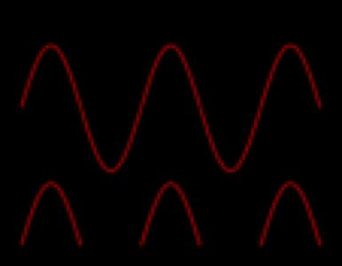
While the turn goes to a vertical position, the current again decreases to zero. During each complete revolution, the current in turn gradually reaches its maximum value, then reduces to zero, and then again reaches the maximum value, but in the opposite direction, and again it reaches zero. So, we saw how an alternating current is created in the rotation, rotates inside the magnetic field.
Mounting and drive
From this we now move on to reality. Now we cut the loop and connect its two ends with two sliding rings, and a fixed brush is placed on each slide ring. If we connect two external load terminals with these two brushes, we get an alternating current in the load. This is our elementary model. Having understood the most basic principle of the alternator, let's now get acquainted with its basic operational principle of a practical alternator. But usually in practical cases the anchor wires are stationary, and between them the field magnets rotate.
Voltage regulator - its purpose is to keep the generator voltage within certain limits. Currently, the generators are equipped with semiconductor electronic (or integral) voltage regulators.
Constructions of voltage regulators:
- hybrid design - the use of radioelements and electronic devices in an electronic circuit together;
- integral execution - all components of the regulator (not counting the output stage) are executed with the help of thin-film microelectronic technology.
The voltage regulator makes a change in the voltage applied to the battery charging by the thermal compensation of the voltage (dependence on the air t). The higher the air temperature, the lower the voltage goes to the battery.
Video presentation of the operating principle of the alternator
These specific phenomena lead to the output of 3φ from the alternator, which is then transferred to distribution stations for domestic and industrial use. The electric system of a motorcycle basically consists of the generator of an alternating current, the battery, the rectifier and a regulator. The alternator consists of a rotor and a stator and generates a three-phase alternating current with the engine running. In the case of three-phase generators, there are two types of rotor.
The drive of the generator is carried out by means of a belt drive, it ensures rotation of the rotor at a speed exceeding the frequency of rotation of the crankshaft by two or three times. In different generator designs, a poly-V-belt or a V-belt can be used:
- V-belt has the prerequisites for rapid wear, (this depends on the specific diameter of the pulley), since the scope of the V-belt is limited by the dimensions of the driven pulley.
- V-Ribbed Belt it is considered more universal, it is applicable for small diameters of a driven pulley, with its help the greater gear ratio is realized. Modern models of generators have in their designs a poly-V-belt.

Generators with a rotor as a permanent magnet
Rotor as a permanent magnet. Rotor as an electromagnet. . The rotor as a permanent magnet is either directly connected to the crankshaft, or driven by a belt. The rotor rotates around the stator or around it with several metallic poles with a copper winding. The rotary motion of the rotor generates an alternating magnetic field, since the windings of the stator coil are alternately subjected to magnetic north and south poles. Thus, a three-phase alternating voltage is generated in the stator coils.
When a key is turned in the ignition lock, a current flows through the brush assembly and the contact rings to the field winding. In the winding, a magnetic field is induced. The rotor of the generator starts to move with the rotation of the crankshaft. The stator windings are penetrated by the magnetic field of the rotor. There is an alternating voltage on the outputs of the stator windings. With the achievement of a certain speed of rotation, the excitation winding is fed directly from the generator, that is, the generator goes into self-excitation mode.
The alternating voltage is converted by a rectifying unit into a constant one. In this state, the generator is engaged in providing the required current for charging the consumers' power and the battery.
The voltage regulator is activated when the load and the speed of the crankshaft change. It deals with the regulation of the time of switching on the field winding. The switching-on time of the excitation winding decreases with decreasing external load and increasing the generator speed. Time increases with increasing load and decreasing rotational speed. When the current consumed exceeds the capacity of the generator, the battery is switched on. On the instrument panel there is a test lamp that monitors the generator's operative state.
Since the electric system of the motorcycle works with direct current, it is necessary to convert the alternating current into a constant one. This task is performed by the rectifier. In turn, the controller ensures that, regardless of speed, the same voltage of 14, 4 volts always reaches the battery. Regulators and rectifiers are separate components in older models, while modern motorcycles are housed in a common enclosure. At high speeds, the output voltage caused by the stator is too high - the drawback of this design - and will destroy the battery due to overvoltage.
Basic parameters of the generator:
- rated voltage;
- rated excitation frequency;
- rated current;
- frequency of self-excitation;
- Efficiency (coefficient of efficiency).
Current-velocity characteristic Is the dependence of the current strength on the generator's rotational speed.
Generators with a rotor as an electromagnet
When the battery's charging voltage is reached, the controller interrupts the charging process. The excess voltage is converted into heat in the regulator itself, but especially in the stator coils. Here are the main drawbacks of this design. Overheating on the stator can lead to the destruction of the insulation varnish and, consequently, to damage to the coils. The regulator becomes very hot and must dissipate heat to the environment through the cooling fins. Corrosion of electrical connections can lead to overloading and failure of the controller, as a result of which the stator can be destroyed. A permanent magnet can lose power after a few years. . Another design, found on motorcycles, uses a rotor with an electromagnet.
In addition to the nominal values, the current-velocity characteristic has other points:
- minimum current and minimum operating speed (40-50% of the rated current is the minimum current);
- maximum current and maximum speed (no more than 10% maximum current exceeds the rated current).
Video
Many drivers do not know how the car generator works and this is a clear problem, both for them and for their transportation. But everything is quite simple and if you show a desire, allocate the necessary amount of time to get to know your car better, and understand the principles of its mechanisms, you can repair the generator yourself
The device of the car generator consists of a large number of elements interacting with each other. I believe that every car enthusiast who respects his car should know everything about the principles of its work. Pulley acts as an intermediary in the process of transferring mechanical energy to the generator shaft from the engine with a belt. The body includes two covers - the front cover, which is located on the pulley side, and the rear one, located on the side of the contact rings. Their purpose is to fasten the stator, also install the generator on the engine surface and place the bearings of the rotor itself. On the back cover you can see the brush assembly, voltage regulator, rectifier and external terminals for connection of the electrical system.
The rotor is a shaft of steel, on which two bushings are placed with a beak-like shape. Between them there is a winding from which the pins are connected directly to the contact rings. The equipment of this group of parts, in general, is made of copper rings of cylindrical shape.
In the stator grooves there is a three-phase winding in which the power of this generator is generated. The part, called the assembly with diodes, in itself combines at once 6 very powerful diodes, which are pressed into three heat sinks. The voltage regulator is a device that maintains a voltage in the previously defined limits during the change of loads. The brush assembly is a detachable plastic construction in which there are special spring-loaded brushes that contact the rotor rings.
Generator mounting
The generator drive is carried out by a temporary transmission from the crankshaft pulley. With the growth of its diameter on the shaft and as the diameter of the same pulley decreases, the generator turns. This means that the consumer can get a stronger current.
All new cars are driven by a poly-V belt. It has special flexibility and permits the installation of a pulley with a small diameter on the generator itself. This gives far higher gear ratios to use high-speed generators. This is done by means of tension rollers in the presence of this fixed-type part. 
Generators are bolted using bolts located in the front of the car engine. In this case, the brackets are used. On the lids there is a tension spring, and also fixing paws. If they are placed with the help of two paws, they will be located immediately on the two covers, but if the paw is one - it will be placed only on the front.
How does it work?
During the engine start-up, the starter will be the main energy consumer.
 The work is accompanied by hundreds of A current, this provokes a drop in voltage throughout the battery. Such a regime provides for the consumption of electricity only with the help of a battery, which at this time is intensely subject to discharge.
After starting the engine, the generator is the main energy source. It is a source of recharging the battery while the engine is running.
If it does not work, then the battery is too quickly discharged and I strongly advise not to forget about it. The car generator helps to provide the current required for charging the battery, as well as the current for the use of electrical appliances. After discharging the battery, the charging current goes down. But the generator will still be a source of power, the battery itself simply smoothes out different pulsations in voltage.
If devices that consume a lot of energy are used, such as a headlight heater, and the rotational speed indicator will be small, the total current consumption may exceed that for which the generator is designed. In this scenario, the load will shift to the battery, so that it will start discharging. As you can see, the principle of the generator is quite simple.
The purpose of the voltage regulator
After studying the device of the generator, many people have a question about the role of the voltage regulator, which once arose in me. Basically, its task is to maintain the voltage within certain limits, in order to ensure the optimal operation of electrical appliances that enter the on-board network.  Each controller has measurement elements that, in fact, act as sensors. In addition, there are executive elements that will perform the function of regulation.
Manufactured by modern technology generators, which are now equipped with any car, are equipped with electronic semiconductor regulators, which are usually built in. There is a variety of designs and schemes, but all have a similar working principle.
Voltage regulators are prone to thermocompensation, which changes the level of voltage applied to the battery for optimum battery charge level, depending on the air temperature under the hood. With its lowering, the voltage rises, but with increasing - the voltage drops. Some of the regulators are equipped with manual mode switches to "winter" or "fly". 
In other words, the controller performs such an important function as stabilizing the voltage level in the process of changing the load level and speed by adjusting the excitation current. In the absence of a regulator, the voltage of the generator itself depends on the rotational speed of the rotor, on the magnetic flux that is created due to the excitation winding. It also depends on the magnitude and current strength in this winding, which are given to consumers. With an increase in the speed of rotation together with the current, there is an increase in voltage.
Electronic regulators measure the excitation current by the inclusion of its winding from the mains, which is fed by electricity, and the length of time during which the excitation winding turns on varies. If, in order to stabilize the entire voltage, it is necessary to reduce the current strength of that excitation, the total time of the excitation winding decreases. Well, if you need to increase, then I advise it to increase.
Video "The principle of the car's generator"
The record shows how the car generators of an alternating current work by what principle.