Welding welder. Contact welding: apparatus and machines, electrodes, photos and video. Production of a spot welding machine.
- Types of welding
- Spot contact welding
- Butt Welding
- Relief welding
- Seam (roller) welding
- Other types and uses of contact welding
Contact welding - the phenomenon of connecting with each other two compressible with great force of metal parts, by heating the place of their contact by an electric current of large magnitude. It is most often used in industry for mass production of the same type of products.
This system allows you to know that the circuit is still charging in order to reach the voltage that we previously set using control or that is unloaded because, as soon as we decided to reduce it. Thus, the energy values that the capacitors will store depending on the charge voltage are as follows. Two thermocouples made of steel micron filaments for experiments with the Seebeck effect.
Ready-made point welding machine with electrodes and accessories. The diagram is shown in the figure. Modified scheme for micro-welding. The tests went well, although with such small diameters, the adjustment of the power and pressure of the electrodes is more critical, and sometimes welding does not come first. It is completely flat, since the protuberances are 1 mm.
The amount of heat released during this process can be calculated according to the Joule-Lenz law: Q = I 2 R Δt, where I is the average current pulse strength, R is the transient resistance, and Δt is the pulse duration. In order for this amount of heat to be sufficient to securely connect the welded parts, the welding current must be large enough: from hundreds to hundreds of thousands of amperes.
They are not adequate, and with planes 3 it is difficult to prevent these thin threads, which easily bend, eventually touch them and even close them at more than one point. On the following pages, we will study in detail the welding process at the engineering level. Despite the fact that it is one of the oldest production processes, it now has a high level of importance in different types of companies; Because of the low cost of application, ease of use and reliability when assembling components.
In the development of this short essay, we will touch on the important elements for an engineer when selecting an integration of an element in the welding process. Elements, which we will take into account in this test at permanent joints by welding, will be. Therefore, we must calculate what will be the fusible element in the union, if required. This advantage of continuity has allowed to create a lot of aesthetically indeterminate, slender and elegant steel structures all over the world. When welding it is easier to make design changes and fix errors during assembly.
This means that the current source (welding machine) must develop sufficient power (1-500 kVA) at an output voltage of 1-15 V and an internal resistance of about 500 μΩ. Electrodes for contact welding should have a sufficiently large cross section and be made of copper alloys with a low specific resistance. The compression force of the parts to be joined can vary within a wide range: from several newtons to hundreds of kilonewtons.
In connection with this advantage is the case of repair carried out during welding on military equipment in combat conditions during the last decades. Another important detail is how to solder softly. Imagine the importance of this fact when working near hospitals or schools or when adding to existing buildings. Anyone who has an almost normal ear who has tried to work in the office a few hundred feet from riveting will accept this advantage.
Less details are used and, as a result, saves time in detail, manufacturing and assembly works. This is the method used to combine metals with metal alloys that melt at relatively low temperatures. It usually differs between hard and soft welds, depending on the melting point and strength of the alloy used. Solder metals from soft seams - lead and embossed alloys, and sometimes small amounts of bismuth. In hard alloys, alloys of silver, copper and zinc, or alloys of copper and zinc are used.

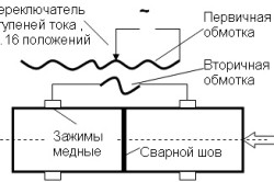
The heart of a welding machine is usually a special transformer for contact welding, the secondary winding of which usually has a small number of turns of wire with a large cross-sectional area. Its primary winding is usually supplied with an alternating voltage, but it can also generate powerful pulses of rectified current. So, for example, the condenser circuit of contact welding works. Pulses appear in it when the charged capacitor of high capacity is discharged to the primary winding of the transformer.
To connect two pieces of alloyed metal, first clean the surface mechanically and apply a layer of flux, usually resin or borax. This chemical cleaning helps the parts communicate more actively, as it removes the metal oxide. In industrial processes, furnaces are often used for heating parts. This type of welding was used more than a thousand years ago, the Phoenicians and the Chinese.
This type unites many welding processes in which fusion occurs between the metals being bonded, with or without the contribution of metal, usually without the use of pressure and at temperatures higher than in conventional welding. There are many procedures, including gas welding, arc welding and alumometry. Other more specific are beam welding, which is carried out in vacuum using an electron or ion beam and light-beam welding, which usually uses a laser beam as an energy source.
If compared with other ways of fastening parts to each other, contact welding has the following undeniable advantages:
- high speed (fractions of a second) of performing individual operations, which allows to ensure high labor productivity;
- simplicity of control over compliance with the optimum process conditions, which allows to ensure reliability and high quality of welding, even with low qualifications of the performers;
- the welding process can be easily mechanized and automated;
- high degree of ecological compatibility.
Types of welding
Back to contents
Welding with gas or a torch uses the heat of combustion of the gas or gaseous mixture, which is applied to the surfaces of the parts and to the metal rod of the feed. The advantage of this system is that it is portable, since it does not need to be connected to an electric current. In accordance with the gaseous mixture used, among others, oxyacetylene and oxyhydroxy welding are distinguished.
Arc welding processes are most often used, especially for welding steel, and require the use of an electric current. This current is used to create an electric arc between one or more electrodes applied to a part that generates enough heat to melt the metal and create a joint.
Spot contact welding
These welding schemes usually involve joining parts at separate points. A schematic illustration of this method of their connection is shown in Fig. 1a. Digit 1 on all diagrams of this figure indicates the parts to be welded. The electrodes are connected to the secondary winding of the welding transformer.
Arc welding has certain advantages over other methods. This happens faster because of the high concentration of heat and, consequently, leads to less distortion at the junction. In some cases, alloying electrodes, which are the starting metals, are used in the form of flux-coated or bare rods; In other cases, a refractory tungsten electrode is used and additional metal is added separately. The most important methods of arc welding are coated electrodes, gas shielding and powder flow.
Arc welding with coated electrode. With this type of welding, the metal electrode, which is electrically conductive, is covered with a flux and connected to a current source. The weld metal is connected to the other terminal of the power supply. When touching the tip of the electrode, a piece of metal forms an electric arc. When the arc is heated intensively, two connected parts and the tip of the electrode are melted, forming the metal of the contribution.
The reliability and quality of the welded joint is determined by the structure and dimensions of the welded points. And they, in turn, depend on the following factors:
- dimensions and shape of the contact surface of the electrodes;
- the value of the flowing welding current;
- time of its course;
- the value of the compressive force (P сж);
- state of the surfaces of the parts to be joined.
Arc welding with gas protection. This is one that uses gas to protect air fusion in the atmosphere. Inert gases used as a protection are usually argan and helium; Active gases are usually mixtures with carbon dioxide. In both cases, the electrode, a bare or flux-covered rod, melts to fill the joint.
The filler metal can be supplied by feeding the bare rod to the electrode. Arc welding with powder flux or underwater arc. This procedure, instead of using a gas or flux coating of the electrode to protect the air connection, uses a bath of powdered material where the parts to be soldered are immersed. You can use several bare wire electrodes and excess powder to reuse, which makes it a very effective procedure.
In this way it is possible to connect both miniature parts having a thickness on the order of fractions of a micrometer, in electronic devices, and steel sheets up to a few centimeters thick in engineering industries.
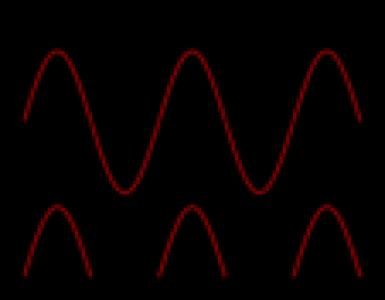
Relief welding is widely used in the automotive industry: welding door hinges and staples to the hood, fasteners connection: studs, bolts and nuts, etc. In electronics, this method is used to attach conductors to small parts. In one cycle, this method of welding allows a large number of welded joints to be obtained.
The heat required for this type of welding is derived from the chemical reaction of a mixture of iron oxide with very fine aluminum particles. The resulting liquid metal is a feed metal. It is used for welding tears and incisions on heavy pieces of iron and steel and is a method used for welding rails or rails of trains.
This method combines all welding processes, under which the pressure is fed without the addition of metals for the connection. Some procedures coincide with fusion procedures, such as pressurized gas welding, when parts are heated by a flame, but differ in that the connection is carried out by pressure and without the addition of any metal. The most commonly used method is contact welding; Others are welding forging, friction welding and other more modern methods, such as ultrasonic welding.
Back to contents
Seam (roller) welding

This type of welding is used when it is necessary to produce sealed welded joints (making gasoline tanks, various tanks, tanks, etc.). Such welding is carried out on specialized machines having one or two pressure roller-electrodes made in the form of disks. When rolling, the rollers tightly compress the joined products and weld them. The thickness of these articles can have values from 0.2 to 3 mm.
This type of welding is carried out by heating metals because of their resistance to electric current flow. Electrodes are applied to the ends of the parts, they are folded under pressure, and through them an intense electric current passes through them. The total area of the two parts, since it has the highest electrical resistance, heats up and melts the metals. This process is widely used in the industry for the production of metal sheets and wires and is very well adapted to automation.
All rights reserved. A joint is understood as the separation between materials that must be welded together. When choosing the welding method used, it is very important to know the types of joints that exist and the processes that need to be performed to make these connections well-made.
Seam welding can be carried out in three ways:
- Continuous, which produces a solid connection that does not contain cast cores overlapping each other. Disadvantages: a strong warming of the rollers, causing the need for frequent over-flowing.
- Intermittent (in the form of separate pulses). By varying the duration of the pulses themselves and the intervals between them, it is possible to change the degree of overlapping of the cast nuclei. The durability of the rollers-electrodes with this method of welding is markedly increased.
- Stepping, during which the current also turns on intermittently, and at the moment of its occurrence, the electrodes stop. Due to these stops, contacts in the current flow area are improved and the risk of hot cracks is reduced.
1.1. Physical processes in contact welding
Elements that can be welded together are many, but the American Welders Association, which is responsible for regulating all welding processes, has classified welded joints. The two main types of welds are fillets and butt welds. There are also welded seams and grooves that are not common in structural work. These four types of welding are shown in the following diagram. Welded welds were more brittle than butt welds, but most structural joints were made with fillet welds.
Contact welding is the process of obtaining an all-in-one connection as a result of heating of metal parts by electric current flowing along them, which involves the compression of parts, followed by melting of the welding zone and cooling.
The machines for contact welding have two main parts: electrical and mechanical. The electrical part consists of a welding transformer of special design, conductive parts and devices for switching welding current. The mechanical part of the installation is a device for impulse compression of parts during the passage of an electric current pulse.
Anyone who has experience in steel structures will understand why corner welds are more common than welded seams. Butt welds or bevelled welds are used when the joined elements are aligned in the same plane. Using them in any situation would mean an ideal assembly of members for connection, which, unfortunately, does not occur in the general and current structure. Many readers have seen how operatives pull and hit steel members to put them in place. When steel elements can overlap, large tolerances are allowed in the assembly using corner joints.
This type of joining parts combines several welding methods, which are characterized by the reliability of welded joints, high level of automation and mechanization, high process productivity, production culture and environmental friendliness.
There are three types of contact welding: butt, spot and suture (Figure 1.1). From the welding transformer T, the current to the connected parts 2 is fed by means of water-cooled electrodes 1. At the welding site 3 welding of the parts takes place due to the evolving Joule heat. The amount of energy Q (J) that is released between the electrodes can be determined from formula
However, butt welds or chamfered welds are common in many joints, such as splices in columns and skate connections from beams to columns, etc. Butt welds account for about 15% of structural welds. The welded seam is a round weld seam connecting two.
Details, in one of which a drill or perforations are made, necessary for welding. A toothed weld is a weld seam formed in a recess or an elongated hole that connects one element to the other through a recess. Welding can partially or completely fill the notch. These types of welds can be used when the elements overlap, and the length of the welding fillet is not. They can also be used to connect parts of an element, as necessary, if necessary, to correct the covers in the composite element.
where Rk is the contact resistance between the parts, Ohm; m is the time of passage of the current, c; Rd is the resistance of the part from the electrode to the welding location, Ohm; I - welding current, A.
The energy required for welding at low resistance values at the point of contact of welded parts can be obtained only at high current values (hundreds and thousands of amperes) flowing through the contact resistance Rk for a short time (units of seconds). To increase the efficiency of contact welding, it is necessary that, when placing the welding installations, the power supplies are as close as possible to the welding location. The voltage on the electrodes of welding machines varies from 1 to 16 V.
The connection of the metal occurs at the point of contact of the welded parts along the plane of their contact. In this place, the resistance will be greatest. The surface of the metal is not perfectly smooth, so the parts to be welded, when compressed, come into contact only at separate points through which an electric current passes. In view of the fact that the area of the points is very small, there is a great resistance to the passage of current, which provides a strong local heating of the metal. Increasing the temperature at the welding site causes an increase in resistance, which accelerates the release of heat and the heating of the metal to the welding temperature. When the metal parts are heated to the plastic state and their compression, welding takes place. The cooling of the metal at the welding point after the disconnection of the current occurs quickly, due to the thermal conductivity of the welded parts and their large area.
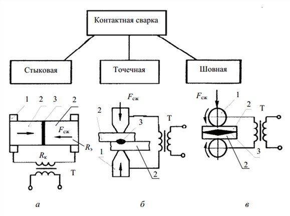
Fig. 1.1. : a - butt; b - point; c - suture; 1 - electrodes; 2 - details; 3 - the place of welding; Fcj is the compression force; R is the resistance of the electrodes; R - resistance of parts; RK - contact resistance; T - welding transformer
In the case of contact welding, the heating depends on the transit time of the current. Heating the parts can be very fast, using currents of great power, and vice versa. Welding modes using high-power currents with a minimum heating time are called hard. They are used for welding alloy steels and low-melting non-ferrous metals, for example, aluminum and its alloys, and have the following parameters: welding current density j = 160-400 A / mm2; force of compression Р = 0,4-1,2 GPa; welding time tcv = 0,1-1,0 s.
The regime with a long current passage and gradual heating is called soft. It is used for welding ordinary carbon steels that are less sensitive to heat during welding, and has the following parameters: j = 80-160 A / mm2; P = 0.15-0.4 GPa; tcv = 0.5-3 s.
1.2. Butt Welding
Butt Welding - a method of contact welding, in which the parts are connected over the entire area of their touch. There are two ways of butt welding - resistance and reflow.
When welding resistance (Fig.1.1a) the welded parts 2 are reinforced in the current leads and compressed with the force Fcj. When current flows through them, the parts in junction 3 are heated to a temperature close to the melting temperature of the metal (0.8-0.9) m.p. Then the compressive force (the draft of the parts) is sharply increased, as a result of which a welded joint is formed in the solid phase.
Fusion welding are also divided into two methods: for welding by continuous reflow and reflow with heating.
During continuous fusion welding the parts approach each other when the welding transformer is switched on, and their contact appears when they are compressed. The joint thus heats up due to the current flow. Then, the compression force is reduced, thereby increasing the contact resistance and reducing the welding current. When the pressure decreases, the continuity of the contact of the parts is replaced by contact at individual points. The efficiency of heating at these points is increased, and the protruding sections are fused.
Fusion of the ends of the welded parts continues until the formation of a layer of liquid metal. After this, a solid metal joint of the welded joint arises due to the application of a small draft force. An extra molten metal, called a bead, is squeezed out of the gap between the parts to be welded.
When fusion welding with heating the parts are preheated by the method of short-term closure of their ends, and then melt. Welding with reflow of joint of parts in comparison with welding without reflowing has a number of advantages: stronger weld, which does not require large machining; less power of the welding machine; less specific electricity consumption; the possibility of welding dissimilar metals.
The design and welding contour of butt welding machines are shown in Fig. 1.2. Butt welding machines are divided into welding method (without melting the joint and with its reflow), purpose (universal and specialized) and installation method (stationary and portable). They differ in power, the type of clamping devices and the mechanism of supply of welded parts.
By the method of settling the parts, welding machines are divided into three groups. The first group of machines is equipped with a lever-eccentric feed and draft mechanism, as well as a device for annealing the metal of the welding zone directly in the clamps of the machine.

Fig. 1.2. Design (a) and welding circuit (b) butt welding machines: 1 - current source; 2 - bed; 3 - current leads; 4 - fixed plate; 5 - sponges; 6, 7 - clamping devices; 8 - mobile plate; 9 - feed drive; 10 - guides; 11 - control equipment; Fсж - force of compression of details; Foc - the force of the draft of the parts
Machines of the second group are intended for welding by reflow and reflow with heating of parts from steels and non-ferrous alloys. They are also used for resistance welding, for which a separate spring drive is provided.
Welding machines of the first two groups have a manual lever feeder and a draft. The welding current is turned off at the end of the draft.
The third group of machines produces continuous fusion welding in an automatic and semi-automatic cycle with preheating of the ends of the welded parts. Machines have an electromechanical drive, which provides continuous reflow and draft Foe. The clamping devices of the components have an air-hydraulic drive, and the feed and draft are hydraulic.
Universal welding machines are used for welding of various parts, and specialized welding machines for welding of the same parts.
1.3. Spot Welding
When spot welding, the connected parts are placed between two electrodes fixed in the electrode holders (Figure 1.1, b). With the help of the push mechanism, the electrodes tighten the welded parts. Then the voltage is applied to the electrodes, and the current passing through the parts heats the welding site to the melting point. With sufficient compression, a welded joint is formed at the welding location. The diameter of the welded point is equal to the diameter of the copper electrodes. At the center of the welding point, the temperature is slightly higher than the melting temperature of the metal to be welded.
The time sufficient for welding one point is determined by the thickness of the welded parts, the physical properties of the welded material, the power of the welding device and the degree of compression of the parts. It ranges from a thousandths of a second (when welding thin sheets of non-ferrous metals) to a few seconds (thick steel parts). The spot welding cycle is shown in Fig. 1.3.
Spot welding systems differ in the method of current supply. The most widely distributed one-point two-sided (normal) welding (see Figure 1.4, a-c). Both electrodes have a working surface providing sufficient current density for point heating of the welding site of the parts.

Fig. 1.3. : 1 - compression of parts by electrodes (P); 2 - holding the electrodes in a compressed state and increasing the pressure at the end of the current pulse; 3 - release of pressure; 4 - turn on the current; 5 - turn off the current; I - current pulse
If there is no possibility of single-point welding, spot welding with an indirect current lead is used. On the one hand, the current is supplied by an electrode with a normal contact surface, and on the other hand by an electrode with a larger contact surface (Fig. 1.4, d). To reduce local residual deformations from welding, additional techniques are used, shown in Fig. 1.4, d, e.
For welding thin-sheet products are used single-sided multipoint welding (Figure 1.4, g). Simultaneous welding of two points with a two-way current lead from a coupled transformer (Figure 1.4, d) allows welding of metal products of large thickness, ensuring high quality of the welded joint.
A lot of designs of machines for spot welding are used in production. They differ in the arrangement of mechanisms for the compression of electrodes, which are subdivided into pedal, electric and pneumatic. Spot welding machines are stationary universal, portable universal, stationary specialized (multipoint) and presses for relief welding of parts.
When spot welding bulky products or when welding in hard-to-reach places, portable welding pincers and welding guns are used.
Multi-spot welding installations successively weld several points in one operation, thus ensuring a high productivity of the welding process. There are two types of multipoint welders.
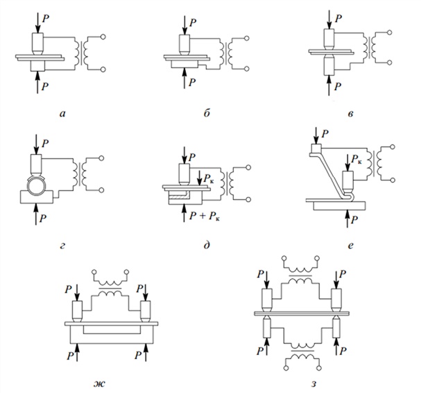
Fig. 1.4. : a-c - single-point double-sided welding; d - welding with an indirect current conductor; d, e - additional welding techniques; ж - one-sided multi-point welding; s - simultaneous welding of two points with a two-way current input from a coupled transformer; P is the compression force; Pk - indirect (additional) compression force
In machines of the first type, only two electrodes are simultaneously lowered onto the weldable sheets, through which a welding current is passed at a given time. In machines of the second type, all the electrodes are simultaneously lowered onto the sheets, the current passes successively through each separate pair of electrodes, performing welding of the parts.
Special welding machine designs are two-and multi-electrode. Such machines provide for special rotary tables, devices for supplying parts and mechanisms for their rotation. Multi-electrode machines are distinguished by methods of clamping the electrodes and supplying current: by sequentially clamping the electrodes through a hydraulic distributor and supplying current with a current distributor; with simultaneous clamping of the electrodes when the transformer is serially switched on in the welding circuit with a current distributor or with simultaneous or group inclusion of several transformers from the primary side. Multi-transformer machines are used in robotic devices equipped with microprocessors. Machines with rotary tables are used when combining operations of assembly and welding, more often on conveyors.
Electrodes used in point machines are installed in the electrode holders, which are fixed in the trunks of the welding machine. Electrode holders are made of brass. They make channels for cooling water. Machines have replaceable electrodes made from cold-drawn red copper or from a special chromium-zinc-copper alloy, which ensure their reliable operation.
1.4. Seam welding
Seam welding - a method of contact welding, in which parts are connected by means of rotating rollers by passing an electric current through the welding site (Figure 1.5). Seam welding machines differ from stationary point welding machines by the type of electrodes (rollers with a mechanical drive). Seam welders have two conductive rollers, one leading and the other rotated by friction when moving the welded sheets. According to the principle of operation, the seam welding is similar to conventional welding.
The seam welding process can have the following modes:
1) continuous movement of rollers with continuous current supply;
2) continuous movement of rollers with intermittent supply of current;
3) intermittent motion of the rollers with intermittent supply of current.
The first mode is used for welding sheets with a total thickness
up to 1.5 mm. If the thickness is thicker, the welded sheets can become delaminated. Moreover, with a continuous supply of current, considerable warpage of the welded sheets can occur. The most common is the second mode: the seams are obtained with a small warpage of the sheets and the smallest consumption of electricity.
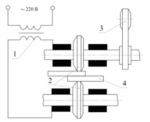
Fig. 1.5. : 1 - welding transformer; 2 - contact rollers; 3 - clamping device; 4 - Weldable parts

Fig. 1.6.
The use of seam welding is most suitable for the manufacture of thin-walled vessels, welded metal pipes and other similar products. The location of the rollers and welded parts when performing various seam welding methods is shown in Fig. 1.6.
1.5. Electrical equipment used in contact welding
Electric contact welding is characterized by high productivity, and in many cases is the only possible and economically feasible way to connect metal parts.
The machines of contact welding, produced by the domestic industry, are divided into general purpose machines and high-performance specialized machines intended for welding specific products.
In installations general-purpose welding welding transformers with twisted cores and windings filled with epoxy compound, as well as control equipment on logic elements with integrated circuits are used. Thyristors are used as current interrupters. Pneumatic and hydraulic equipment is characterized by high performance and reliability.
By the nature of the current, transformation or accumulation of energy, the following types of machines are distinguished:
a) single-phase alternating current industrial or low frequency;
b) direct current (with rectification of current in the secondary circuit);
c) three-phase current, low-frequency with a thyristor converter;
d) with the accumulation of energy (in capacitors, electromagnetic systems, rotating masses).
The contact welding installations with rectification of current on the low-voltage side of the power transformer have a number of technological advantages when welding large-dimension sheet structures from aluminum alloys, titanium, heat-resistant and stainless steels. In comparison with low-frequency machines they are more versatile, economical and reliable in operation. The use of direct current in seam machines can significantly improve the welding speed without reducing the quality of the welded joint, and in multi-electrode machines, alternate or group feeding of the electrodes can be performed from a single current source.

Fig. 1.7. : 1 - the detail; 2 - secondary circuit; 3 - the transformer; 4 - the switch; 5 - contactor; 6 - rectifier; 7 - switch; 8 - energy storage; 9 - the transformer; 10 - control equipment
The scheme of the electric power part of the contact welding machines ensures the obtaining of the required welding current from 2 to 10 kA from the 380 or 220 V mains supply at the power source of power from 75 to 750 kV • A and more.
The block diagram of the electrical part of the contact welding machines is shown in Fig. 1.7. To feed the welding current to the workpiece 1, a secondary circuit 2 serves. The shape of the curve and the value of the welding current strength are obtained by converting or accumulating electrical energy from the power frequency network using transformers 3, 9, rectifiers 6 or energy storage devices 8 (for example, capacitor banks) . Power converters (transformers, rectifiers) are connected to the network or connected to the energy storage device 8 by means of a contact 5-6, and the necessary alternation of the current polarity in the welding transformer is provided by the switch 7. The welding transformer 3 provides high current values at low voltage. The welding current is regulated by a step change in the secondary voltage of the transformer 3 by switching the number of stages of its primary winding by the switch 4. The welding current is controlled by the control equipment 10 by changing the switching point of the contactor 5 valves (rectifiers 6) relative to the phase of the mains voltage in each half-wave. The control equipment provides the specified sequence and duration of all or part of the welding cycle operations.
AT single-phase alternating current machines (Figure 1.8, a) the welding transformer T is connected to the electrical network by a knife switch through the fuses 2 and the switch of the PS stages by means of the contactor-breaker Ex. The moment of switching on the breaker breaker Пр is determined by the control equipment of the AC, and the current in the secondary winding of the welding transformer has a sinusoidal or close to it shape (Figures 38, b, c), and in the presence of special current modulators it is possible to obtain a current pulse with a smooth amplitude variation 38, d), which significantly improves the quality of the welded joint.
Contact welding machines have a power factor of 0.5 to 0.6. An increase in the energy performance of single-phase machines with the same current values and dimensions of the welding circuit is possible by lowering the frequency of the secondary voltage of the welding transformer of the installation.

Fig. 1.8. The electrical diagram of the power part of the alternating current machine (a) and the shape of the welding current pulses I2 (b-g): AU - control equipment; T - transformer; PS - stage switch; Pr - contactor-breaker; 1 - electric network; 2 - fuses
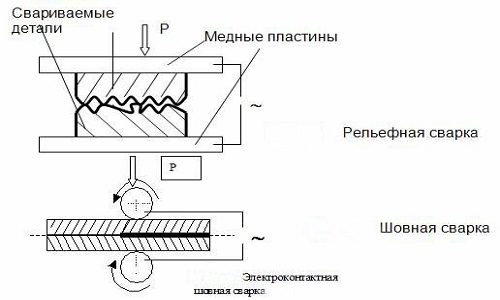
In the applied dC welding machines (three-phase with a rectifier in the secondary circuit) (Figure 1.9), the primary winding is connected in the "triangle" scheme, and the secondary circuit is connected to the secondary winding connected to the star through the valves 1-3 (Fig. The general electrical diagram of the welding machine is a three-phase rectifier. In such machines, the problem is straightening very large welding currents.
Control of the machine - switching on and off of the three-phase step-down transformer T and current regulation is carried out by thyristors connected in series with the primary windings. With instantaneous commutation, the current through the thyristor VSi and the primary winding of the transformer connected to it passes for one third of the period (n / 3), when the voltage in this phase is greater than in the other two (at point K of Figure 1.9, b). In this third period, the current through the other two thyristors can not pass, since the potential of their anodes is lower than the total potential of the cathode. In the next third of the period, the current will pass through the second VS2 gate, etc. The current from one gate to the other (Figure 1.9, c) occurs at the moment of intersection of positive half-sine waves of the voltage (points K, L, M in the diagram in Figure 1.9 , b). Similarly, the commutation of the current passes through the welding circuit (Figure 1.9, d, d). Despite the unipolar flow of the current in the primary winding (Figure 1.9, c),
the magnetic fluxes in the rods of the three-phase magnetic system (Figure 1.9, e) do not have a constant component (the induced magnetization flux that occurs when there are no valves in the primary winding), since the algebraic sum of the magnetic fluxes in the three-rod magnetic system is zero.

Fig. 1.9. : a - the electric circuit of the three-phase rectifier; bd - diagrams of currents and voltages observed during commutations in the welding circuit; e - directions of magnetic fluxes in the rods of the magnetic system
Demagnetization of a rod occurs by the magnetizing forces of the windings located on the other two rods. Due to the connection of the primary windings according to the "triangle" scheme and the presence of valves not only in the primary, but also in the secondary circuit, the sum of the ampere-turns located on the same winding pin is practically zero at any time.
Advantages of DC welding machines are: uniform phase loading, wide possibilities for regulating the shape and duration of the current pulse, as well as obtaining a multi-pulse mode; less power consumption in comparison with single-phase machines, especially at large outlets and when welding materials with low specific resistance; the absence of influence of the ferromagnetic masses introduced into the welding contour on the values of the welding current.
AT low-frequency welding machines The transformation of a three-phase current of an industrial frequency into pulses of a current of low frequency (5-20 Hz) is used. This is achieved by briefly switching the power ignnitron rectifier into the primary winding of the welding transformer T of the machine (Figure 1.10). Advantages of such machines are: favorable form of welding current pulse - its smooth growth and decline; uniform load of three-phase network with reduced power consumption due to reduced inductance of the circuit; increased power factor in comparison with single-phase machines.

Fig. 1.10. : T - welding transformer; PP - batch switch
AT welding machines with energy storage During a pause, there is a slow accumulation of energy in the drive with a low power consumption from the network and a short-term use of it during the welding process.
To ensure the specified productivity of contact welding machines and high welding quality, it is necessary to strictly adhere to the specific time of the welding current flow for each welding cycle. This is achieved with the help of the appropriate elements of the control schemes of welding installations: welding current switches, time controllers. Welding current switches are available in several types: mechanical switches, asynchronous electromagnetic contactors, synchronized electromagnetic contactors, ignitronic switches, etc. The mechanical current switch has a system of movable and fixed contacts that are included in the primary circuit of the welding current transformer. The mechanism of contact drive is connected with the device of clamping of welded products. At low switching speeds, the contacts of the mechanical switch are burned and require frequent replacement, which limits their use in low-power contact welding machines.
Asynchronous electromagnetic starters used in welding machines have a limited lifetime of contacts, since they break the operating current at an arbitrary point of the sinusoid.
The time of the welding current flow is provided by special time controllers, which are divided into electromechanical, electropneumatic and electronic.
With the electric drive of contact machines, electromechanical time controllers are usually used, the working bodies of which are cams acting with the rotation of the motor shaft by their protrusions to the mechanical current switches.
In contact welding machines with a pneumatic compression mechanism, electropneumatic time controllers are used. The circuit of the electronic time controller is shown in Fig. 1.11. The control circuit of the electromagnetic contactor KC of the welding transformer T1 is activated by the closing of the contacts of the key K, and its deactivation is carried out automatically by the electronic circuit after a certain period of time. Before closing the contacts of key K, the current from the terminal of the network flows through the adjustable resistance R - the grid of lamp L, the normally closed contacts of relay E and the coil of the contactor KT to pole 2 of the network. The shunt resistance of the capacitor is charged when the current flows through the lamp L.

Fig. 1.11. : 1 - the first pole of the network;
2 - the second pole of the network; CC - electromagnetic contactor; T1 - welding transformer; Т2 - the transformer of the time controller; K is the key; A is a lamp; Э - the contact of the relay is closed; CT - coil of the contactor; R - adjustable resistance; С - condenser
Since the grid current is small, no contact of the QD contact occurs. The grid current to the lamp stops when the key K is pressed, while the grid is connected to its external part through a negatively charged capacitor and a relay coil.
Contact welding plants are mass consumers of electricity, therefore their rational use is an important direction of energy saving. The best results are given by the following measures: improvement of welding technology, including preparation of welding parts; acceleration of the assembly of parts, optimization of the cycle of compression of parts, limitation of idling of power supplies, periodic revision of contact connections in the welding current circuit; setting norms for the consumption of electricity for welding operations.
Let us summarize the foregoing. Contact welding in machine building is one of the most demanded ways of joining parts, because it provides a high welding speed, the required quality of the welded joint and can be easily automated. One of the advantages of contact welding is the minimum heat loss.