Winding excitation of the car generator. How to check the excitation on the generator
Many motorists wonder how to turn on the generator without using the battery. This is necessary for those motorists who often go for long distances, and the car without recharging will last at the expense of the battery not more than 2 hours. Let's find out how.
The main thing about excitation effect
As you know, the voltage generated by the genome at various engine speeds is regulated by the excitation windings. The current is maintained at a constant voltage of 13.8-14.2 V.
The procedure in these cases for obtaining 380 V is to connect the generator to 440 V and adjust the terminal voltage in the potentiometer of the voltage regulator to get the desired value. Table 1 - Relationship between voltages, currents and power in a three-phase system.
In connection with this, the winding of each phase has two ends that are withdrawn from the engine. This type of connection requires 6 available terminals in the motor terminal box and is suitable for any double rated voltages, provided that the second value is equal to the first multiplication by.
Note that the voltage above 600 volts is not considered a low voltage and enters the medium voltage range, where the standards are different. Figure 5 - Star-delta connection. In vacuum, the armature voltage depends on the magnetic flux generated by the excitation poles, or on the current flowing through the excitation winding. This is due to the fact that the stator is not controlled by current, so the armature response is zero, the effect of which is to change the total flow. The relationship between the generated voltage and the excitation current is called the vacuum characteristic, where we can observe the saturation state of the machine.
To provide the car system (numerous consumers) with a current, a regulator or LV is provided. It happens on domestic cars and some foreign cars, as a rule, is built inside the generator. In everyday life, this regulator is called a chocolate bar, a tablet, etc.
The gene is connected to the positive terminal of the battery via the output "30". It is also called a plus, "B" or "BAT". As for the negative output, it is denoted as "31" or minus. Also in everyday life there are other signs of it: "D", "B-", etc. The tablet terminal used to supply power from the car network with the ignition on is output "15" or "S". Finally, the output calculated to supply current to the charging test lamp is designated as "61" or "D +".
Under load, the current through the armature conductors creates a magnetic field, causing changes in the intensity and distribution of the main magnetic field. This change depends on the current, cosine and load characteristics, as described below. The induced magnetic field creates two lagging 90 ° poles lagging behind the main poles, and these poles exert a counterforce on the induced poles, and the mechanical power is expended to support the rotation of the rotor. Due to the loss of voltage in the armature windings, it will be necessary to increase the excitation current to maintain the rated voltage.

If the recharging of the battery stops, this in most cases indicates a deterioration of the chocolate. However, there is no need to despair, because it will be enough to apply voltage to the windings, ie, to turn on the generator to reach the store or the nearest service station.
Figure 2 - The chistoresistive load. The inductive load effect is demagnetized. Inductive loads store energy in their field of the inductor and completely return it to the generator, without exerting a braking torque on the inductor. In this case, the mechanical power will only be needed to compensate for the losses. Due to the demagnetization effect, to maintain the rated voltage, a significant increase in the excitation current will be required.
Figure 3 - Purely inductive load. The reaction field of the armature will, therefore, be in the same direction of the main field and with the same polarity. The induced field in this case has a magnetizing effect. Capacitive loads store energy in their electric field and completely return it to the generator, and also do not exert any braking torque at the anchor, as under inductive loads. Due to the magnetization effect, it is necessary to reduce the excitation current to maintain the rated voltage.
So, to get to the right place without exposing the battery to a deep discharge, you need to remove the chocolate and excite the gene.
Generator circuit
The question arises, how to connect the generator? In order to be able to excite the gene, without the use of batteries, it is recommended to carefully study the scheme and the principle of the functioning of genes of various modifications.
Fig. - Pure capacitive charge. Fig. - Changing the excitation current to maintain the DC voltage of the armature. In these cases, the induced field can be decomposed into two fields, one transverse and another demagnetization or magnetization. Only the transverse field has a braking effect, thereby consuming the mechanical power of the drive machine. The magnetizing or demagnetizing effect is compensated by a change in the excitation current.
Synchronous generators are built with smooth or protruding pole rotors. Fig. - Rotor with smooth poles. In these cases, there are so-called interpolar regions, where the air gap is very large, making the protrusions of the poles visible. The physical meaning of the components of the quadrature and the straight axis is as follows: the projecting gear has the preferred direction of magnetization determined by the protrusion of the field poles. The permeability along the polar or straight axis is much larger than along the interpolar or quadrature axis.
It is also important to understand why a gene is needed, what it does specifically. In other words, a gene is an electric machine that serves to convert mechanical energy into an electric current. Thanks to the gene, the battery is recharged and all electric consumers in working position are supplied with current.
The gene is located in the front of the engine, and is driven by a crank shaft. In hybrid cars, the gene carries out the work of the starter. It is noteworthy that the same scheme is observed in some "high-grade" cars equipped with a stop-start design.
Fig. - Schematic diagram for a synchronous machine. Usefulness of knowledge about reactions The effective rotor circuit on a straight axis, in addition to the winding of the main field, is formed by damping rods. Considering a machine initially operating in a vacuum and a sudden three-phase short circuit occurring at its terminals, a short stator current wave can be observed in the figure below, which can be obtained on an oscilloscope.
Figure 2 - Symmetric short-circuit current in a synchronous machine. The pumping reaction. This is the reactive value of the machine that corresponds to the current that circulates in the armature during the first cycles, as can be seen in Figure 2. Its value can be obtained by dividing the armature voltage value before a current failure at the beginning of the fault, for a sudden load and nominal frequency.
It becomes clear that automobile genes can have two schemes, two constructive forms. Their difference in the difference between the layout of the fan, the rectifier block and the drive pulley. Also, generators with different schemes differ in geometric dimensions.
General parameters of both types of generators remain unchanged. Any gene must have a rotor or inductor, stator and other parts.
This is the reactivity of the machine, corresponding to the current that circulates in the armature after a period of a short-circuit transient period that continues for more cycles. Its value can be obtained by dividing the voltage in the armature corresponding to the beginning of the transition period by the corresponding current under the same load conditions.
Synchronous reactance This is the value of the reactance of the machine, corresponding to a constant short-circuit current, i.e. at the end of the transient period of short circuit. Its value can be obtained by voltage at the armature terminals at the end of the short-circuit transient period divided by the corresponding current.
Let's consider the scheme of an autogenerator of domestic "classics". This gene was put on almost all models of old domestic machines.

 Now consider another scheme, more modern. In particular, it is used at the G-8 and other automodels from the VAZ.
The importance of knowing these reactions is that the current in the stator after the occurrence of an error in the terminals of the machine will have values that depend on these reactions. Thus, the characteristics of the machine in the face of the malfunction and its consequences can be known.
A synchronous generator is the only component of an electrical system that has three different reactive states, the values of which are subject to inequality. The power of the synchronous machine is expressed. Fig. 2 - Power curve in synchronous machines.
Electromagnetic power, which is the power transmitted by the rotor from the generator to the stator, can be expressed. The second term of the expression is additional because of the difference in air gap resistance, which does not depend on the excitation of the machine.

 And this is a scheme, how the gene is connected and, in fact, how it functions.

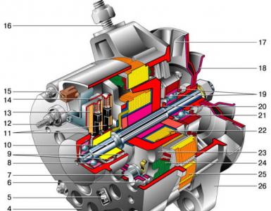
The main function of the gene rotor is the creation of a magnetic field. To do this, the shaft has a winding or VO (exciter). VO is located on the beaks or protrusions of the pole halves. The shaft also has a contact group consisting of 2 copper rings. Through them there is a voltage on the VO. The rings are soldered to the terminals of the VO.
Distortion can be determined for each harmonic in relation to its amplitude as a percentage of the fundamental. The total harmonic distortion can be calculated using the equation. Figure a shows the waveform taken between the phase in the generator. The estimated distortion was 2.04%.
Deviations or variations of the sinusoidal wave can occur in any part of the wave: positive, negative or when crossing zero. The degree of variation, expressed as a percentage of the peak value of the sinusoidal reference wave, is the deviation of the factor.
Note. Quite rare, but nevertheless, there can be not copper, but steel or brass rings.
In addition, on the rotor shaft found a place for the impeller fan (the number of them depends on the design of the model). In the same place is fixed VAP (pulley drive).
Another knot of the rotor is bearings.
As for the stator, it performs the function of creating an alternating voltage. The core and winding were found in it. The metal core is assembled from plates.
Figure 3 - Amplitude deviation. The deviation factor can be calculated as. This is a cyclic change in the amplitude of the voltage caused by the oscillation of the regulator or a cyclic change in the load. The voltages of the three-phase system lag 120 °. If this lag is different from 120 °, this value will be an imbalance.
The voltage imbalance is the difference between the maximum and the lowest line voltages and can be expressed as a percentage of the average phase voltage. These are short bursts of voltage that appear sporadically and can reach hundreds of volts. Figure 4 - Transition from voltage.

There are 36 grooves in the stator, which serve for laying the winding. In total it turns out to establish three windings, thereby, providing a 3-phase connection.
It is interesting that the windings are placed in the grooves in two ways - a wave or a loop. And windings are interconnected either in the "star" or "triangle" scheme.
They are permissible maximum voltage deviations and are usually expressed as a percentage of the nominal voltage, for example. When operating in a vacuum at nominal speed and without excitation voltage, the synchronous generator will show the residual voltage due to the residual magnetism present in the magnetic core of the pathogen. These voltage levels can lead to serious and life-threatening accidents. It is not recommended to manipulate the machine while the rotor is in motion.
Length of body 1 = short; 2 = mean; 3 = Long. The power code of the generator. They are usually driven by diesel or gas engines. Exciter with permanent magnets, which facilitates priming under any conditions. Easy maintenance of short-circuit current.

A rectifying unit or WB is needed to rebuild the current values produced by the gene. It converts the sinusoidal current into a permanent car-borne network.
WB - it's just a plate, the track, effectively removing heat. They have built-in diodes. The WB contains six power semiconductor diodes. For each phase there are two diodes, of course, one for plus, and the other for the negative terminal of the gene.
Single or double bearing and horizontal mounting. Easy maintenance, guaranteed strength of machines, easy access to diodes and voltage regulator. Encapsulated voltage regulator with built-in fuse installed in the junction box.
They are usually controlled by hydraulic, steam or wind turbines. Brushless or gentle excitement. With or without auxiliary exciter for supply voltage regulator. Digital voltage regulator with serial output, power factor control, parallelism, etc.
Brushes - a node that provides current transmission to the contact rings. The brush assembly consists of graphite elements, actually the brushes themselves, the springs-holders and the holder. In genes of the modern type, the brush assembly creates, together with the regulator (chocolate), a single unit.
Tablet - designed to maintain the gene current in certain values. Modern regulators are electronic (single) or hybrid. If in the course of a hybrid version, then the radio components and electrical appliances are introduced into the circuit, if the integral (single) - all elements are performed with the help of TMT (microelectronics).
Power supply voltage regulator through the generator or external source. Horizontal or vertical structural forms. Different kinds of cooling. In particular, we can cite. In these generators, the field in the rotor is fed by direct current through the brushes and manifold rings, and the alternating output voltage for the load supply is output from the stator. Usually in this system the field is supplied by an exciter, called a static pathogen. The output voltage of the generator is kept constant within its nominal characteristics through a voltage regulator, which constantly checks the output voltage and acts on the static exciter.
The generator drive is operated by the rotation of the belt drive. Thus, it provides the inductor with the rotation at the speed that is necessary (it is known to exceed the speed of rotation of the crank shaft by several times).
So, on most models of genes, VO is connected through a separate group consisting of 2 diodes. The latter are also called rectifiers, they prevent the passage of the discharge voltage of the battery with a standing ICE.
When activated at the rated speed and the exciter is disconnected from the rotor, the priming process begins with the residual voltage of the small generator. Some advantages and disadvantages of this kind of excitement. It is not recommended to use in sensitive and telecommunication charges because of the possibility of generating radio interference due to contact of brushes and rings. Therefore, it must not be used in explosive atmospheres.
In these generators, the direct current for field feeding is obtained without the use of brushes and collection rings using only magnetic induction. To do this, the generator has a component, called the main exciter, with a rotating armature and a fixed field. The armature of this pathogen is installed on the shaft of the generator itself. It also has a set of rotating diodes, also mounted on the generator shaft, for a DC direct current source. This set of diodes receives an alternating voltage from the rotor of the main exciter, the voltage is induced by the stator of the main exciter, which is supplied to the DC from the voltage regulator.
Note. If the windings are connected in the "star" scheme, then at the zero terminal 2 additional power-type diode are put, which allows to increase the power of the gene by as much as 15%. WB is mounted in the gene scheme by means of electric soldering or mechanical fixation.
A regulator or a tablet in the generator is a very important thing. It is she who is responsible for the stabilization of tension. And this, as is well known, is very required when changing the rotational speed of the crank shaft and internal combustion engines. Stabilization of chocolate is made on the machine, by affecting the VO. Thus, the tablet controls both the frequency of the voltage signals and the duration of the pulses.
Interesting moment. The tablet changes the current going to charge the battery due to the thermal compensation of the voltage. In other words, the warmer the surrounding, the less current goes to the battery.
How to excite a gene
So, what must be done to excite the generator? As mentioned above, it is necessary to dismantle the tablet from the generator, since the malfunction has arisen in it. Next, connect the positive terminals of both devices, and cut the negative output in the chocolate bar. In the process of assembly, connect it with the mass of brushes.
From the terminal "30" of the gene isolate the wire, connect the indicator "15" to the output circuit, no more than 15 W. This applies to the genes of the G222 series. If the aggregates of other models, then it is necessary to excite, connecting the indicator to the output "B".
Self-excitation of the generator can be imagined and so.

In the above diagram, the leftmost arrows indicate diodes. They are installed only in generators of modern models, in older units they do not exist. More precisely, the circuit without the presented diodes is considered classical, and with them - modernized, modern.
On some models of genes, anchors mean the presence of brushes. They also removed, drilled a tablet. One contact directly goes to the anchor through the diodes to plus, as seen in the diagram, the second contact - to the minus (the lowest arrow).
Accordingly, on the diagram it is noted: plus and minus.
The current will not start immediately, ie, not from a low speed. Somewhere, if you look at the tachometer, the voltage will begin to develop after 4000 rpm. In other words, we gas up to 4 thousand turns, a current appears. If we go down to 1 thousand revolutions per minute or less, the tension disappears, it will be necessary to gas again. Approximately this is the principle of current generation during self-excitation.
On some car models the engine is installed low-speed. In this case, you have to do something with the pulleys to increase the initial speed of rotation. For a normal engine, everything should be fine.

Go ahead. The output is not 12 volts, this should be known from the beginning. Without a regulator, the gene will give out everything that it can, down to 20-30 volts. For example, during the start and up to 36 volts comes. This can be checked by a light bulb of this voltage, connected to the outputs. Then it goes down to 20 volts.
The scheme, of course, can be improved. For example, cut the capacitor into the positive wire that goes to the anchor. This is done so that when the engine speed falls, do not allow the voltage to drop. A good capacitor can also be placed at the output to smooth out the first surge of voltage and adjust, smooth out the recessions.
Realizing this scheme, it is important to remember the issuance of a large voltage. It's not 12 volts, you can easily burn the light bulbs, the computer and all the car electricians in principle.
A warning. In the mode of self-excitation, the gene will give everything that it can without any restrictions, which is fraught with overheating for itself. A little more stress, and write a panegyric to the generating device. Therefore, this method is applicable only as a forced measure, again, if you stayed on the road and need to get to the nearest service station.
How to pay for gasoline in two times less
- The prices for gasoline grow every day, and the appetite of the car only increases.
- You would be happy to cut costs, but is it possible in our time to do without a car !?
A generator is not just some kind of knot. In fact, it is an electrical machine that converts energy into electricity. The generator provides the car with a recharging, without which it can stay on the move for no more than 1-2 hours due to the battery. Find out how the excitation of the generator occurs in the car.
How is excitation in the gene
Electricity or electric power in the generator occurs when a conductor moves through a magnetic flux inside. The current also occurs when the magnet moves, and the conductor remains stationary.
Without theoretical explanations and conclusions, one can imagine the excitation of a gene like this:
- The electricity from the battery is supplied to the winding of the gene. Electric current first take brushes and copper rings.
- The cut-off relay is a special thing that does not allow the battery to discharge when the generator stops. When the driver turns on the ignition, the voltage is applied to the cutoff relay, it draws the internal elements of the generator, thereby closing the contacts. It turns out that the relay in this case - an effective adapter, connecting the winding of the gene with the battery.
- On the dashboard in the car there is a bulb. It tells the driver when the battery genome begins charging. When the ignition is turned on, it is lit until the voltage is coming from the battery and goes out when the power-up process goes back.
What is CB and ARV
Gene excitation system is a complex of various devices, including: pathogen, ARV, CGR, UBVV, excitation device, as well as additional dough-meters.
ARV - this is nothing like a regulator, functioning completely on the machine. SGS is a means that extinguishes a magnetic field. UBVV is a device that makes rapid excitation boosting possible.
The exciter itself is the source of supply (IP) of the winding with constant voltage. In this case, the PI can be a gene itself, together with semiconductors and a rectifier block (a diode bridge).
ARVs are used in a synchronous gene. Here they perform the function of increasing the physical stability of the generating device. It is customary to classify ARVs on devices with proportional step and strong pitch. Some are able to change the current by the inadequacy of the stator voltage, while the latter react in a broader sense of the word.
When the current decreases, for example, when closing, forcing is provided. It implies a rapid increase in excitation, which affects the stopping of voltage drops and maintains stability.
Correction and acceleration significantly improve the reliability of the relay.
When the generator trips, which can also be caused by internal closures, the unit should be de-energized. To do this, it is enough to extinguish the magnetic field, which will make it possible to reduce the size of the damage to the stator winding.
To quench the magnetic field means, therefore, to rapidly reduce the magnetic flux of excitation of the gene to a value close to 0. Simultaneously, the EMF of the aggregate decreases.

The damping of the magnetic field is carried out with the help of AGP - special automatic devices operating from the relay. They help to activate resistance.
In generators operating on the principle of thyristor excitation, the reduction of the magnetic field is realized by the method of switching the main gates to inverter order. Thus, the energy saved in the winding will be transmitted to the driver or the diode bridge.
It is characterized by CB with a nominal voltage (NT), but it can be different.
- 100 or 600 V, if it is a matter of excitation at the terminals of the winding.
- 100 or 8000 A, if it is a question of HT, which is directly in the winding, and corresponds to the normal, standard operation of the generator.
It should be noted that the NT of the pathogen should account for a fraction of the percentage of the HT generator. As a rule, the values in 0.2-0.6 percent of the nominal power of the gene are considered.
With regard to the speed of the pathogen, it depends on the rate of increase in current on the winding of the inductor (rotor).
CB (excitation system) must be calculated depending on the operation of the ARV. In other words, without ARV work is allowed, but only for the time needed for repair or replacement. In other cases, the use of ARV is mandatory.
Note. If CB, nevertheless, functions without ARV, then an additional protection system should be provided. This RDU and other means, capable of providing excitation and auto-extinction of the generator field.
The SV is required to provide current in a continuous mode, exceeding the generator's HT by at least 10 percent.

CB is also semiconductor. In this case, it must have a PBC (internal storage mode).
It is important that the protective devices providing stability during overvoltages are of repeated effect.
| Composition of the excitation system | What does the excitation system provide? |
|---|---|
| rectifier transformer | initial excitation |
| sequential booster transformer | idling |
| thyristor converter (TV 8-2000 /) 050-1U4) | inclusion in the network by the method of precise synchronization in normal modes and self-synchronization in emergency modes |
| converter cooling system | gG operation in the power system with loads from idle to rated and overloads |
| aggregate of initial excitation (AN B-2) | underexcitation within a stable generator |
| automatic excitation regulator (АУ1Г type ARV-SD) | boosting of current and voltage excitation |
| blanking panel | effective field damping |
| relay panels | deexcitation at normal plant stops |
Varieties of SW
CB is divided into 2 groups. They are classified according to the method of excitation. Distinguish between independent type of CB (SWNT) and dependent (CBSS).
To SWNT include all the pathogens that are associated with the generator shaft. In fact, they are able to generate voltage in an independent mode.
For the group of the SVZT take pathogens, grasping the voltage directly from the ends of the main generator. The current flows through the transformers of a special type.

The SWNT looks more profitable, since in them the current generation does not depend on the electric circuit.
Interesting moment. On genes with weak power, separate, independent generators capable of producing a current are used as causative agents. They are connected to the main gene's shaft (synchronous).
Other advantages of SWNT:
- High percentage of performance;
- High rate of current rise;
- The possibility of replacing thyristors that failed, without stopping the generator.
However, SWNTs also have drawbacks related to the device itself. For example, if the speed of increasing excitation is not too high.
Besides:
- Weak in SWNT look like sliding contacts, since the voltage to them is fed through brushes.
Today the most demanded SV with semiconductor diode bridges. They are built on a 3-phase circuit, they use a minimal amount of thyristors arranged in order.
As for the diode bridge circuits, they are 1-group and 2-group. One rectifier is implemented in the first case, two - in the second.
The current source in the SWNT is a synchronous gene that finds its place between the inductor and the upper bracket of the main generator.
![]()
SVZT is less reliable than the first system, since the work of the pathogen here is completely dependent. In other words, the exciter in this case will only work if it receives a current from the network. And in the network, as a rule, there are often shortages that violate the stable operation of CB. It turns out an extra load on the SVTT, which should provide forcing the voltage in the winding.
However, in some cases, the RCTs have advantages over self-sustaining systems. They are expressed in the simplicity of the scheme. The disadvantage is, as it was said, impermanence of work, which is most noticeable in high-power machines.
In the opinion of experts, if the duration of repair is implied, then the SHCT will best prove itself.
Check excitation
The main symptoms that prove the nonoperability of CB on the generator are the indicators of external characteristics. To put it another way, if the voltage does not flow through the generator terminals, then the unit must self-excite according to the principle. If this does not happen, there is a problem.
The work of the generator on diesel units is clearly visible. They get a smaller, than usual fuel dose, as soon as the generator develops a small power. Thus, the diesel plant remains underloaded.

It is clear that when the fuel supply to the cylinders is reduced, the speed of movement also decreases. On it (speed) it will be possible to determine the voltage drop of the generator, and hence its excitation.
If the product of the voltage increases in the generator, then the magnetic saturation of the CB should not increase, otherwise the insulation strength of the electric machine will not survive. Limited in some values can also be called the generator current, which in case of increase will lead to burnout of the armature winding.
How to pay for gasoline in two times less
- The prices for gasoline grow every day, and the appetite of the car only increases.
- You would be happy to cut costs, but is it possible in our time to do without a car !?