DIY leak protection system. Do-it-yourself protection against water leaks for your home. Classification of leakage protection systems
Emergency situations when water fills the entire house can happen to anyone. A special alarm system can prevent flooding. The sensor works to identify the problem and shut off the water supply to the apartment or house.
Then it can happen in any house or apartment. The reasons could be a broken pipe or a drain problem. In this case, not only the plumbing and furniture in the house may suffer, but also the apartment on the floor below. A water leak sensor will help prevent an unpleasant situation.
Flood alarms work much simpler than other sensors. The system is quite fast, it will help not only identify problems, but also turn off the water. This option is good when the owners are away from home.

Causes of the flood:
- Leaking bathtub or sink drain;
- Broken water supply pipe;
- Clogged drain, which leads to obstruction of the drain and overflow of water over the edge of the plumbing;
- A pipe bursts when liquid gushes out like a fountain;
- Burst of heating pipes.
Problems with the heating system are especially dangerous if it is a central system. Water moves through high-pressure pipes and has a high heating temperature. Even if the owners are at home, it is very difficult to stop the hot flow.
In just a few minutes, a house can fill with 5 cubic meters of hot liquid.
In this case, you will need to urgently shut off the coolant supply. But, in order not to put your life in danger, it is easier to install a flood sensor. He does not panic, unlike people, and regularly performs his duties.
One of the reasons for a sudden flood may be a water hammer in the pipeline. The causes, consequences and methods of protection are described in the article:.
The principle of operation of the Anti-Flood system and its classification
The operation of the system lies in the difference between the electrical conductivity of water and air. The design of any sensor contains a pair of electrodes. When liquid gets on them, the resistance decreases and the circuit closes.

The information on the controller is decrypted. Next, the controller signals the closing of the solenoid valve. It is installed at the entrance to the riser.
The closing period lasts from 2 to 30 seconds. This is influenced by the type of system chosen.
The inlet valve will be stopped in operation until the cause of the leak is detected. After setting up the controller, the system will return to its original form. The stationary alarm operates autonomously. Only if there is a problem will you need to intervene in the system.
Classification of the Antipotom system:
- For the number of electric cranes;
- For the method of reporting the problem;
- For the option of data exchange between the sensor and the controller.
Normally, the number of electric taps is at least two. This is due to the installation of sensors for hot and cold water. But if desired, the number of taps can be increased.
Water leakage alarm circuit
You can use different versions of the leak protection system. The most popular are “Neptune”, “Aquaguard”, “Ardvino” and “Gidrolock”. They work on a similar principle. The devices are installed on ball mixers with an electric drive. Safety features not only shut off the water, but also alert the user to the presence of a problem using sound or light. These mechanisms get along well with the smart home system.

Elements of the leakage sensor circuit:
- Controller;
- Water leakage sensor;
- Ball water tap with electric drive.
The controller is used to decipher the signal that comes from the sensors and the voltage of the electric drive. The element powers the remaining parts of the structure and signals a problem. The controller can be installed anywhere. The main thing is that no water gets on the device.
The leakage sensor reacts to moisture and sends a signal to the controller. To connect it, only safe power sources are used so that there are no emergency situations when accidentally touching the plates. Installed in places where there are likely to leak: next to plumbing fixtures.
Operating the sensor involves wiping the plates with a damp sponge every three months. This is a preventative measure.
Ball valves are used to block the operation of a water supply or heating system. Protective measures will be carried out until the unpleasant situation is eliminated, when the outflow of fluid is ensured. The device is installed after the water valves. Installation must be carried out by professionals, as the connection requires the use of a special power cable.
Installation of a flood sensor from the manufacturer
Assembling a security system is not difficult. The control unit is installed on the wall. Then the batteries are installed. If necessary, make supply connections.

Sensor locations:
- Under the bath or shower;
- Under the sink and toilet;
- Under washing machines and dishwashers;
- Behind the radiators;
- Immediately at the point of entry and installation of the meter.
Then the signal cable is laid. Next, connect the sensors to the controller. If the system is wireless, then an action is performed with each sensor.
The ball valve is installed at the hot and cold water inlets. It is also provided at the inlet of each riser or at the outlet of the boiler if the system is autonomous. connected to the control unit. Each one is given its own number and program.
This completes the installation process. You can safely go on vacation without fear of flooding your neighbors. The system is quite reliable, there is no doubt about its effectiveness.
Nuances of placing the water sensor on the floor
There are many options for using sensors. There are many tasks that a small device can handle. But the system itself is quite simple.

Purposes of using sensors:
- Bathroom flood detection;
- Preventing leaks in basements where groundwater levels are high;
- Control of kitchen plumbing;
- Installation in areas where there is a high risk of flooding of houses;
- Troubleshooting heating system leaks.
Sensors are installed in the most dangerous places. These are corners under plumbing fixtures and radiators. However, accidental contact with water on the device should be kept to a minimum. Otherwise, the alarm will go off constantly for no reason.
Small leaks at pipe joints can be repaired using special sealants. What types of sealants there are and how to use them, you will learn from our material: .
DIY water leakage sensor assembly
Thanks to a simple mechanism, you can build a wired sensor with your own hands. The leak detector consists of simple elements that can be at hand. You may have to buy a few things, but the cost of the device is still petty. It is worth understanding that a homemade system only signals a problem; it will not be able to shut off the water.

Necessary materials for work:
- 3 V battery – CR1632 device is used;
- Transistor BC816 or BC517 with NPN composite;
- 1-2 MOhm resistor;
- Piezo emitter included with generator;
- Plastic bottle.
The assembly process provides step-by-step instructions. First you need to familiarize yourself with the design diagram. Next, the resistor is soldered to the piezo emitter. Then the transistor is connected. The circuit is connected to the batteries using blue electrical tape.
Such an aqua guard will only work when water gets on the body. Therefore, the battery will last quite a long time.
To create the body you will need a large bottle from which the neck is cut off. The bottom is made on one side of the bottle, which is secured with glue. You will need to make 2 holes to insert the housing. Holes for the piezo are also made in the lid. Screw the cap onto the neck and check the functionality of the system.
A water leak sensor is reliable protection against flooding in your home. You can control its operation by turning it on and off. The mechanism itself may differ depending on the manufacturer, but the main elements remain the same. Interestingly, you can build a primitive sensor on your own. To do this, you do not need to have special knowledge or materials.
The unpleasant situation of flooding your home, as well as apartments located on the lower floors, can be avoided by installing a system that shuts off the inlet valves when moisture appears on the floor of the room. Such devices, designed specifically for domestic use, have long existed on the market under the general name “leakage protection systems.” The widespread distribution of these devices is hampered by their high cost, due to the presence of imported components and assemblies. Do-it-yourself leak protection , does not have this drawback and can be made from parts that can be found in any garage.
Let's consider two types of devices: mechanical and electronic. The first device is very simple to make. The second will require some knowledge of electronics and skills in working with a soldering iron. Both devices have been repeated many times by home craftsmen and have earned the reputation of being inexpensive and effective systems for protecting against water leaks.
Homemade paper-spring mechanism

Water leakage protection device invented by A.V. Rudik.
The homemade mechanism, which was invented by the inventor Alexander Vladimirovich Rudik, is somewhat reminiscent of a mousetrap. It consists of a cleverly crafted metal body, a spring, a paper strip and a cable attached to a ball valve that shuts off the water supply. This mechanism works as follows: when the paper tape gets wet due to moisture getting on it, it breaks and releases the tensioned spring. Compressing, the spring pulls the cable, which, in turn, closes the valve.

Alexander Rudik's mechanism is a bit like a mousetrap
The advantage of this device is that no intervention is required in the water supply system, since ball valves already installed in it are used. In addition, if necessary, nothing prevents the valves from being manually closed.

Installing the cable
The leakage protection device can be installed anywhere: in the kitchen under the sink, in the bathroom or in the toilet. Its design allows the use of two cables to simultaneously stop the supply of cold and hot water. In this case, the mechanism does not require any maintenance.
Manufacturing a leakage protection mechanism
To make a leakage protection device, you will need:
- Bench vice;
- Hacksaw for metal;
- Drill;
- Hammer
- Pliers;
- Electric sharpener.
The materials you should stock up on are sheet metal (preferably galvanized or stainless steel). You will also need: a cable, a suitable wooden block measuring 360x50x30mm, a spring, paper, screws, and pushpins.

Metal sheet cutting diagram
The base of the mechanism is a block, the edge of which is cut along the short side at an angle of 93°. Elements 3, 4, 5, as well as a spring and a cable are mounted on it.
A paper strip is used as a sensitive sensor, which is attached to a wooden base with buttons.

Plain paper is used as a signaling device
To make element No. 3, you can use a durable block measuring 150x20x50mm. A blank cut from a sheet is bent around this block, slots are made to install the cable, and then removed from the wooden fixture.
It is better to make the third and fourth structural elements from stainless steel, since this material has a more slippery surface. The places where the parts need to be bent are shown in the drawing with red lines.

Install a cable in the slot of parts 4a and 4b
A cable is installed in the slot of parts 4a and 4b. Then parts 4, 4a, 4b and the spring must be connected from below with a screw.
Mechanism adjustment
It is convenient to manufacture and adjust the device using a simple device that imitates part of a water supply system. To do this, you will need a 20 mm pipe with a threaded part on which you need to install a ball valve.

Bracket for attaching the mechanism to the pipeline
Using such a device, you can check and adjust the operation of the mechanism right in the workshop. You will also need a pipe when drilling holes in elements 2 and 2a. To do this, install a pipe between them and clamp the parts in a vice. At the same time, make sure that the crane handle (element 1 and 1a) is in the closed state, and the grooves for the cable and element 2 are aligned. After this, they begin to drill through holes in elements 2 and 2a.

The tap handle will allow you to adjust the operation of the mechanism right in the workshop
Element 5 has a hole for a finger (for installing a spring) and a hole for a hook. By scrolling through the turns, part 5 can be used to adjust the spring stiffness.

The mechanism is in a “charged” state
The tension force of the spring in the working position must be at least 10 kg. The main condition: the force exerted on the paper tape should be 1-1.5 kg. To measure its value, you can use a household spring scale (“canter”). If necessary, the amount of force can be changed by decreasing or increasing the angle at the short end of the bar. Elements 3.4 should have the same angle in the contact area.

Spring bracket with pin hole
A good spring is obtained by cutting off the required piece from a door spring, which are sold in any hardware store. You can use a bicycle cable by shortening it to the required length.
To check the functionality of the assembled system, the paper tape is moistened with water. When wet, it should break and release the spring mechanism.
Requirements for installing a mechanical leakage protection system
If the mechanism has worked, subsequent installation of the paper tape should be done only after complete removal of moisture from the surface of the device.
The cable should have a length of no more than 2 m, and its numerous bends should be avoided (no more than one bend at a right angle is allowed).
The bracket must be firmly attached to the pipe, so it is better if the pressure pipeline is made of metal pipes.

This is what the drive mechanism looks like
The ball valve must be of good quality. Resistance to the closing force and jerking while turning the handle are not allowed.
Operation of the leakage protection mechanism (video)
Electronic anti-flood system
The electronic system consists of at least three blocks. This is a leakage sensor installed on the floor of the room, a control unit and an actuator.
This system works as follows: when moisture appears, the circuit between the sensor electrodes is closed. This commands the control unit to supply voltage to the electric drive, which shuts off the water supply. The leakage sensor and control unit can be made independently. As an actuating mechanism, you will need an electric valve or a ball valve with a servo drive.
Sensor manufacturing
The simplest leakage sensor is two conductors located at some distance from each other. However, you must agree that exposed wires on the floor of a bathroom or toilet will look, at a minimum, ridiculous, and at a maximum pose a risk of electric shock. Therefore, you can make a sensor by etching tracks on a printed circuit board from foil PCB, and use a doorbell button as a housing.

Using a Doorbell Housing as a Leakage Sensor
The work should be performed in the following order:
- Cut the board to the size of the button;
- Using the LUT method or using photoresist, it is necessary to etch tracks on the surface of the boards;
- Tin the printed conductors using a soldering iron;
- Solder staples to the conductors as legs;
- Connect the connecting wire;
- Install the printed circuit board into the bell button housing.

PCB diagram
There is no need to dismantle the button itself; it can be used to close the line to check the functionality of the system.
Electrical diagram of the control unit
The system is powered by a small 12V battery. The main requirement for a power source is its low self-discharge. Since the current consumed by the circuit in standby mode is negligible, the battery will have to be recharged literally a couple of times a year.
The ball valve closing control circuit works as follows. In standby mode there is no current through the sensor, the transistors are closed, the relay is de-energized. When water appears at the base of transistor VT1, a bias voltage appears, as a result of which the transistor opens and supplies power to the base of the more powerful transistor VT2. In turn, the open transistor VT2 controls an electromagnetic relay, which supplies power to the actuator.

Example of a control circuit for closing a ball valve
In the electrical circuit, you can use transistors of the n-p-n structure with any marking. Transistor VT2 should be of medium power. Resistors R1, R2 are low-power.
The advanced electrical circuit is shown in the following figure. It is designed to connect two geared motors.

Example of an improved electrical circuit
Executing mechanism
Of course, you can assemble the actuator yourself using a suitable gear motor and limit switches. However, it will be easier and more reliable to purchase a ball valve with a factory-made servo drive. When purchasing such a device, make sure that its design includes limit switches that open the circuit in extreme positions.
Of course, the price of these devices is much higher than their plastic counterparts, but the reliability of their operation is not satisfactory.

Actuating mechanism
After connecting the sensor, control unit and electric valve to the power source, the system is tested. To do this, pour a little water onto the sensor installation site.
It’s always good when the engineering systems of your apartment work as normal, but unforeseen situations happen when everything doesn’t go according to plan. The water supply system in the apartment consists of pipes, connections and water fittings. The connections are reliable, but due to the fact that this is a connection, a leak may occur, which can result in expensive repairs, and as a rule, not only at home, but also at neighbors. In order not to invest a large amount in repeated repairs and repairs from neighbors, it is better to invest a small amount in a water leakage system. My house is new, but I decided to play it safe, especially since the renovation was not completed yet.
There are different systems, but as a rule they all work on the same principle. At the inlet there are valves with a drive, which close when there is a signal from the sensors about a leak. I couldn’t afford a very expensive system, so systems with wireless sensors and GSM communications were immediately removed from the list.
After searching the Internet, I found several systems and settled on the domestic manufacturer SPYHEAT and its Triton water leakage control system.
The kit comes in a small cardboard case with a handle. The suitcase contains four boxes and instructions. Two boxes contain ball valves with an electric drive, the third box contains a set of four sensors, and the fourth contains a controller.

Ball valves are made of brass, electric drives are protected by a housing made of orange plastic. There is a handle on the body for manually closing the tap. To use the handle, you must pull it towards you and turn it until the ball valve closes or opens. The indicator in the window indicates the position of the damper.


The controller is housed in a plastic case and can be installed in a standard Legrand panel. On the front panel of the controller there is a liquid crystal indicator and control buttons.
“On/Off” button – a button to turn the system on and off (the system turns on and off by long pressing this button).
“Reset” – reset the emergency condition. After pressing this button, the controller gives a command to open the ball valves, regardless of the state of the sensors. If, 3 minutes after opening, the emergency situation (water on the sensors) persists, the controller will continue to operate according to the “emergency” algorithm.
“Reverse” – changing the position of the tap to the opposite. If the tap was closed when this button was pressed, the controller will open it and vice versa.
“Block” – blocking the operation of the controller. The blocking will remain in effect until all sensors become dry, after which the controller will go into standby mode.
“Lock” – locks the controller keys from accidental pressing. It is carried out by simultaneously pressing the “on/off” and “block” buttons; the “lock” is displayed on the display (a very good function, especially when there are small children in the house).


The sensors are plastic with a hole in the middle. The sensor can be secured to the floor using a screw or dowel. The length of the wire is 3 m, but can be increased if necessary.

Installing the system is not particularly difficult and anyone can handle it. First, you need to determine the places of probable leakage, these usually include sections of pipes with a large number of connections, places where water taps and household appliances are installed, such as a dishwasher and washing machine. I decided to install sensors in the place where the washing machine is installed, under the kitchen sink, in the sanitary unit (near the input unit) and in the bathroom. It is better to attach the sensors to the base so that they are parallel to the floor plane. If possible, you can fasten it using a small self-tapping screw directly to the base; if you can’t use a self-tapping screw, you can drill a hole for the dowel and secure it using it.

According to the instructions, first of all you need to connect the built-in battery; it is responsible for the operation of the system in the event of a 220V network disconnection. To do this, you need to unscrew two screws from the back of the controller and connect the contacts of the battery and the controller. The battery in the system uses a lithium-polymer with a capacity of 1000 mAh. When charged from the “box”, without connecting to a 220V network, the battery was able to open and close the taps three times, but I didn’t try further.
I decided to install the controller near the water distribution unit in the sanitary unit. To do this, I used a crown to cut a hole with a diameter of 64 mm in the cabinet and install the controller.

I called a plumber to install ball valves into the water supply system. Installing taps is no more difficult than installing meters, so it does not cause any particular difficulties. In my case, the plumber installed the taps after the meters, which, it seems to me, is not entirely correct, since it is better to install them before all places of possible leakage. Perhaps in the future I will correct this oversight.

According to the instructions, you need to connect all wires to the controller. All connection points are marked and this procedure does not cause any difficulties. I would like to draw your attention to the fact that the wires from the taps can be combined and only three connected to the controller, not six. The system is also designed to connect a grounding wire, so if there is one, it’s better to connect it.

After installing the system, you need to check its functionality; to do this, you need to wet the sensor. As soon as the sensor senses moisture, the controller sends a signal to the drives and the ball valves automatically close. At the same time, a sound and light signal is heard. The procedure for closing the tap takes approximately seven seconds (checked several times). It is unlikely that a tragedy will happen in such a short time.
After checking the performance of the system using all sensors, I left the system on duty. The system automatically opens and closes the valves periodically, thereby preventing souring of the ball valves. If necessary, by pressing the buttons on the controller, you can forcibly shut off the water supply. This function is very convenient when, for example, you are going on vacation, press a button and the taps will automatically close. Although it is recommended to periodically close and open the inlet taps, few people do this, as a result of which they become sour and sometimes it is not possible to close them.
As a result, we get a fairly budget-friendly, efficient system that will help avoid large financial losses in the event of a leak.

What else would you like to note? The Triton water leakage control system is a domestic development and is entirely produced at a plant in the Russian Federation. The system has a 5-year warranty, but I think it will last much longer.
I would like to express special gratitude to the team at spyheat.ru for their advice in installing the system and for their good positive attitude.
The article presents a pragmatic approach to creating one of the elements of a Smart Home - economical flood protection (anti-leakage) based on a universal home automation controller.
The main differences from the solutions to this problem previously presented on Habré are ease of implementation, relatively cheap + you don’t need to be a programmer to repeat it. True, you will still have to solder, but only 2 times.
Introduction
On Habré, as a resource for technically active people, where people in need go for advice and solutions to problems, there are many articles on the topic of Smart Home.And often in the comments there are regrets that no one has yet come up with a simultaneously powerful, easy-to-learn and economical way to implement a Smart Home for ordinary people. Either you need to solder, then you need to code, often in different languages: for the microcontroller, for the web, and so on.
And so that he could take it, buy spare parts-cubes for inexpensively and personally launch it himself - this rarely happens.
So I decided to insert my 5 cents, since it seems that I just came across one of the options for implementing a Smart Home, which may be suitable for many pragmatically minded consumers.
I will tell you using the example of implementing flood protection, although already on the same controller I have a security alarm system, temperature recording and automatic shutdown of the necessary sockets when leaving home.
So, according to my “Maslow’s pyramid of needs for a Smart Home” (c) - the importance of alarms and flood prevention is at the same level as the importance of alarms about intrusion or smoke.
Maslow's pyramid of needs for a smart home

For the scale of the tragedy can be terrifying:
Due to the fact that I recently acquired a universal smart home controller and have already implemented more important functionality, I decided that it was time to “lay down the straws”.
Problem
So, if a water leak was detected, I wanted to receive an alert (SMS and/or email) and have the water supply to the apartment automatically shut off. And also be able to open and shut off the water manually, including remotely via the Internet.Solution
There are a number of ready-made kits for a complete or partial solution to this problem, but, firstly, they are, to put it mildly, expensive, and secondly, having a universal smart home control controller in your hands, you can do all this yourself and it will be no worse, and even better, because that everything will be integrated into a single system and will interact exactly as I want, and not as the system manufacturer decided. And considering that the most expensive part of the system already exists (the controller), we get rid of duplication and redundancy.The current structure of my Smart Home system. The components directly involved in the Anti-Leak system are highlighted in red.

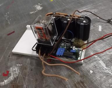
The desktop layout of the applied part of the anti-leakage system looked like this:

I now get hot water by heating cold water in a boiler. Therefore, only one pipe needs to be closed.
If necessary, the system can be simply expanded and the second pipe can be shut off simply by adding another valve and connecting it in parallel to the radio relay.
Leak sensor
The most difficult moment in the entire system.The trouble is that if the issues of controlling intrusion and the appearance of smoke or gas are easily solved by standard sensors, then with the control of water leakage everything is somewhat different. The list of compatible sensors on my universal controller does not yet include a water leakage sensor. At least it wasn't...
A search on the hub quickly showed the path of least resistance: take a standard wireless reed switch and instead of the reed switch, or rather parallel to it, bring out the wires with contacts and short them with water.
This approach has a number of disadvantages: one of the main ones is the oxidation of non-gold-plated contacts over time.
 I previously read on the Internet that there are other ways to detect water leaks, for example, non-contact ones, but the cheapness, efficiency and simplicity of implementing the option described above interrupted the flight of engineering thought towards innovative approaches.
The basis was taken from the Chinese wireless magnetic contact (reed) sensor MD-209R. In my case, I chose a relatively cheap clone sensor compatible with the PowerCode transmission protocol (from Visonic), since this is one of the wireless protocols supported by my controller.
I soldered 2 wires parallel to the built-in reed switch, the short circuit of which actually triggers the sensor.
So, after some simple manipulations with a soldering iron, this is what happened:

Motorized valve
 As a valve that shuts off the water, you can use any valve that has an electric drive and an appropriate size connection to the pipe.
 I tested my prototype on a Chinese valve with an electric drive for a 1/2-inch pipe.

The valve's motor drive design automatically cuts off power to the coil after opening or closing. Thus, there is no need to use commands from the controller to remove the voltage through the radio relay after the operation has been completed.
Radio relay
To supply power to the drive, I purchased this two-channel radio relay from the list of those compatible with the controller on ebay. Type YKT-02XX-433
The 1527 encoder chip, so beloved by Chinese manufacturers, is installed inside.
It contains 10-amp relays, so, in principle, they can switch almost any household load up to 250V. Limit 2 kW.
To control the electric drive, this is more than enough, since the valve drive is powered by 12 V and, according to the passport, consumes only 4 W, and only when the valve state changes.
This radio relay can operate in several modes, one of which is exactly what we need: mutual blocking of channels. In this mode, when the relay of one channel is turned on, the relay of the other channel is automatically turned off. Thus, we “almost in hardware” protect against the simultaneous supply of voltage to the “opening” and “closing” of the valve electric drive solenoid due to any glitches.
Connection diagram for valve, receiver:

Control

As the “brains” of the system, I used Nanoserver NS1000 - a universal controller from the domestic manufacturer 1-M Smart Home.
Controller capabilities that are used in one way or another in this project:
Support for low-cost wireless sensors and radio relays.
Execute scripts offline (even without internet).
Notification of events via SMS and email.
Elementary compilation of “scenarios” for the operation of the system without writing code.
Ability to control devices from a smartphone (Android).
Management via WEB.
Keeping “logs”.
Scenarios
When setting up the controller, you need to consider the following nuance:The reed sensor sends a response message when it opens, but we need it to when it closes. Accordingly, in the scenario launch condition, you need to indicate not turning on the sensor, but turning it off. And not by condition, but by change. To prevent notifications from repeating cyclically.
Condition for starting scenario 1: If the “Leakage sensor” channel is turned off.
Script steps:
. Alert “Master, we have a flood!”
. Enable the “Close water valve” channel
And a script to open the valve upon command from a key fob or smartphone:
Condition for starting scenario 2: If the Channel “You can open the water valve” is turned on.
Script steps:
. Enable the “Water valve open” channel
In the WEB interface of the cloud service it looks like this:

To manually control devices, you don’t need to “program” anything - after adding it to the system, control of each device automatically becomes available from your Personal Account through the WEB interface and from the Android application.
View of the WEB control panel for a Smart Home via the Internet:

Appearance of the Android application

What is the result?
The goal has been achieved. When the leak sensor is triggered, I receive an SMS notification like “Master, we have a flood!” and the valve automatically closes in less than 30 seconds.Also, I have the opportunity to not automatically open and close the valve by pressing the buttons on the key fob, from a smartphone or from a browser via the Internet.
The activation of each sensor and device is recorded in the log log.
At the same time, there was no need to write code and repeating this solution independently is quite accessible to most (of course, not counting the installation of valves on pipes).
Setting up the system, knowing what you want, takes about 10 minutes. Including activation of the sensor and radio relay, creation of all scenarios.
It is clear that in the form in which it is presented in the photographs, in reality it will not be able to work for a long time and reliably.
The valve drive power supply, radio relay, and the sensor itself must also be placed in plastic boxes with at least some degree of protection.
Plus, various thoughts are already arising on the development of the system, for example, duplicating the notification for the light alarm, periodically “training” the valve so that it “does not stagnate”, etc. By the way, I personally have serious doubts about the need for the backup power function of the solenoid valve, which some “purchased” anti-leakage kits boast so much about.
In other words, appetite comes with eating.
The good thing is that to increase the functionality, you don’t need to call “certified” specialists to tweak something in the system. You can easily do all this yourself, thanks to the simplicity of the principles of setting up a universal controller.
A little about prices:
Nanoserver NS-1000 - $44Magnetic contact sensor MD-209R - $13
Radio relay - $10
Valve - $15
Total (excluding delivery) = $82
Not that cheap. But this is if you do not take into account that the nanoserver is used not only for the anti-leakage function. After all, it has a security and fire alarm system and other capabilities...

P.S.
During the implementation process, having already purchased the valve, I discovered that there are electric actuators that are installed on conventional manually operated ball valves.An additional and important bonus of this approach is that if something happens, you can return manual control of the valve in a few minutes.
I immediately didn’t want to embed additional shut-off valves into the water supply system and I ordered such a drive. I am waiting.
Update 2:
For now, the controller manufacturer has announced a leakage sensor.


Judging by the information, the sensor uses a non-contact principle for detecting the appearance of water, which in itself is quite unusual. It is also interesting in that it is not “tailored” to a “brand” and can be used not only with the 1-M Smart Home system, but also with any system that works using the PowerCode protocol. In fact, it transmits a message similar to the MD-209R sensor, which I used for my anti-leakage.
The price seems to be comparable too - $9.9.
Water is life. If it is in the tap, or in the heating radiator, this is good. And if it is on the floor of your apartment, or on the ceiling of your neighbor below, this is a big financial and moral problem. Of course, it is necessary to regularly check the water supply and heating system for corrosion or cracks in plastic pipes. However, a water breakthrough usually occurs suddenly, without any sign of impending danger. It’s good if at this moment you are at home and not sleeping. But, according to the law of meanness, leaks occur at night, or when you are not at home.
Simple rules for dealing with this problem (especially for old housing stock, with worn-out networks):
- Regularly inspect water pipes and heating system elements for defects, spot rust, tight connections, etc.
- When leaving home, close the entrance valve on the riser.
- Outside the heating season, close the taps on the radiators (if any).
- Use a leakage protection system.
We will consider the last item on the list in more detail.
How to signal a water leak
The solution to the problem came into everyday life from the yachting world. Since the ship's lower tier rooms (especially holds) are located below the waterline, water regularly accumulates in them. The consequences are clear, the question is how to deal with it. It is irrational to assign a separate sailor on watch for control. Then who will give the command to turn on the sump pump?
There are effective tandems: a water presence sensor and an automatic pump. As soon as the sensor detects that the hold is full, the pump motor turns on and pumping occurs.

The water sensor is nothing more than a regular float on a hinge connected to the pump switch. When the water level rises by 1–2 cm, the alarm and the sump pump motor are triggered at the same time.
Comfortable? Yes. Safely? Of course. However, such a system is unlikely to be suitable for a residential building.
- Firstly, if the water reaches a level of 1–2 cm over the entire area of the room, it will run through the threshold of the front door onto the landing (not to mention the neighbors below).
- Secondly, a bilge pump is completely unnecessary, since the cause of the breakthrough must be immediately found and localized.
- Thirdly, the float system for rooms with a flat floor is ineffective (unlike watercraft with a keeled bottom). By the time the “required” level for operation is reached, the house will fall apart from dampness.
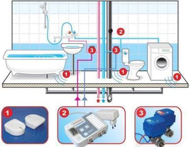
Therefore, a more sensitive alarm system against leaks is needed. This is a question of sensors, and the executive part comes in two types:
1. Alarm only. It can be light, sound, or even connected to a GSM network. In this case, you will receive a signal on your mobile phone and will be able to remotely call an emergency team. 
2. Turning off the water supply (unfortunately, this design does not work with the heating system, only water supply). After the main valve, which supplies water from the riser to the apartment (it does not matter whether it is before or after the meter), an electromagnetic valve is installed. When a signal is sent from the sensor, the water is shut off and further flooding is stopped. 
Naturally, the water shut-off system also signals a problem in any of the above ways. These devices are offered in a wide range by plumbing stores. It would seem that material damage from a flood is potentially higher than the price of peace of mind. However, the majority of citizens live by the principle “until thunder strikes, a man will not cross himself.” And more progressive (and prudent) homeowners make a water leakage sensor with their own hands.
Operating principle of leakage sensors
Speaking about the block diagram, everything is very simple. A certain element fixes the liquid at the point of its placement and sends a signal to the executive module. Which, depending on the settings, can give light or sound signals, and (or) give a command to close the valve.
How the sensors work
We will not consider the float mechanism, since it is not effective at home. Everything is simple there: the base is fixed to the floor, a float is suspended on a hinge, which, when floating, closes the switch contacts. A similar principle (mechanical only) is used in the toilet cistern.
The most commonly used sensor is a contact sensor, which uses the natural ability of water to conduct electrical current.

Of course, this is not a full-fledged switch through which 220 volts passes. A sensitive circuit is connected to two contact plates (see illustration), which detects even a small current. The sensor can be separate (as in the photo above), or built into a common housing. This solution is used on mobile autonomous sensors powered by a battery or accumulator.

If you do not have a smart home system, and water is supplied without any solenoid valves, a simple sensor with an audible alarm can be used as a starting option.
Homemade sensor of the simplest design
Despite its primitiveness, the sensor is quite effective. Home craftsmen are attracted by this model due to the cheap cost of radio components and the ability to assemble it literally “on the knee”.

The base element (VT1) is an NPN transistor of the BC515 series (517, 618 and the like). It supplies power to the buzzer (B1). This is the simplest ready-made buzzer with a built-in generator, which can be purchased for pennies, or removed from some old electrical appliance. The power required is about 9 volts (specifically for this circuit). There are options for 3 or 12 volt batteries. In our case, we use a Krona type battery.
How the scheme works
The secret is in the sensitivity of the collector-base transition. As soon as a minimum current begins to flow through it, the emitter opens and power is supplied to the sound element. A squeak is heard. An LED can be connected in parallel, adding visual signaling.
The signal to open the collector junction is given by the very water whose presence needs to be signaled. Electrodes are made from metal that is not subject to corrosion. These could be two pieces of copper wire, which can simply be tinned. Connection points in the diagram: (Electrodes).
You can assemble such a sensor on a breadboard.

Then the device is placed in a plastic box (or a soap dish), with holes made in the bottom. It is advisable that if water gets in, it does not touch the circuit board. If you want aesthetics, the printed circuit board can be etched.
The disadvantage of such a sensor is different sensitivity to different types of water. For example, distillate from a leaking air conditioner may go unnoticed.
Based on the concept: an inexpensive autonomous device, it cannot be integrated into a single security system for your home, even a homemade one.
A more complex circuit, with a sensitivity regulator
The cost of such a scheme is also minimal. Performed on the KT972A transistor.

The operating principle is similar to the previous version, with one difference. The generated signal about the presence of a leak (after opening the emitter junction of the transistor), instead of a signaling device (LED or sound element), is sent to the relay winding. Any low-current device, such as RES 60, will do. The main thing is that the supply voltage of the circuit matches the characteristics of the relay. And from its contacts, information can be sent to the actuator: smart home system, alarm system, GSM transmitter (to a mobile phone), emergency solenoid valve.
An additional advantage of this design is the ability to adjust sensitivity. Using a variable resistor, the collector-base transition current is regulated. You can adjust the response threshold from the appearance of dew or condensation to the full immersion of the sensor (contact plate) in water.
Leak sensor on LM7555 chip
This radio element is an analogue of the LM555 microcircuit, only with lower energy consumption parameters. Information about the presence of moisture comes from the contact pad, indicated in the illustration as a “sensor”:

To increase the response threshold, it is better to make it in the form of a separate plate connected to the main circuit with wires with minimal resistance.
The best option in the photo:

If you don’t want to spend money on buying such a “limit switch,” you can etch it yourself. Just be sure to cover the contact paths with tin to increase corrosion resistance.
As soon as water appears between the tracks, the plate becomes a closed conductor. An electric current begins to flow through the comparator built into the chip. The voltage quickly increases to the operating threshold, and the transistor (which acts as a key) opens. The right side of the diagram is command-executive. Depending on the execution, the following happens:
- Top diagram. The signal on the so-called “buzer” (beeper) is triggered, and the optionally connected LED lights up. There is another use case: several sensors are combined into a single parallel circuit with a common sound alarm, and the LEDs remain on each block. When the sound signal is triggered, you will accurately determine (by the emergency light) which unit has triggered.
- Bottom diagram. The signal from the sensor is sent to an emergency solenoid valve located on the water supply riser. In this case, the water is shut off automatically, localizing the problem. If you are not at home at the time of the accident, the flood will not happen, and material losses will be minimal.
Information: Of course, you can also make a shut-off valve with your own hands. However, it is better to purchase this complex device ready-made.

The circuit can be made using a printed circuit board layout that is equally suitable for both LM7555 and LM555. The device is powered by 5 volts.

Important! The power supply must be galvanically isolated from 220 volts so that dangerous voltage does not enter a puddle of water during a leak.
In fact, the ideal option is to use a charger from an old mobile phone.
The cost of such a homemade product does not exceed 50–100 rubles (for the purchase of parts). If you have old components in stock, you can reduce costs to zero.
The case is at your discretion. With such a compact size, finding a suitable box will not be difficult. The main thing is that the distance from the common board to the contact plate of the sensor is no more than 1 meter.
General principles for placing leakage sensors
Any owner of a premises (residential or office) knows where the water supply or heating communications are located. There are not many potential leak points:
- shut-off taps, mixers;
- couplings, tees (this is especially true for propylene pipes that are connected by soldering);
- inlet pipes and flanges of a toilet tank, washing machine or dishwasher, flexible hoses of kitchen faucets;
- connection points for metering devices (water meters);
- heating radiators (can leak both over the entire surface and at the junction with the main line).

Of course, ideally, the sensors should be located precisely under these devices. But then there may be too many of them, even for the DIY option.
In fact, 1-2 sensors per potentially dangerous room are enough. If it is a bathroom or toilet, as a rule, there is an entrance door threshold. In this case, water is collected as if in a pan; the layer can reach 1–2 cm until the liquid spills through the threshold. In this case, the installation location is not critical, the main thing is that the sensor does not interfere with moving around the room.
In the kitchen, sensors are installed on the floor under the sink, behind the washing machine or dishwasher. If a leak occurs, it will first form a puddle in which the alarm will sound.
In other rooms, the device is installed under heating radiators, since water supply pipes are not laid through the bedroom or living room.
It would not be superfluous to install the sensor in a niche through which risers of pipelines and sewers pass.
The most critical points of water breakthrough
With uniform operating pressure, the risk of leakage is minimal. The same applies to mixers and taps, if you open (close) the water smoothly. The weak point of the pipeline system manifests itself during water hammer:
- when closed, the water supply valve to the washing machine creates a pressure that is 2–3 times higher than the nominal value of the water supply system;
- the same, but to a lesser extent, applies to the locking fittings of the toilet cistern;
- Heating radiators (as well as their connection points to the system) often do not withstand the pressure testing carried out by heating supply companies.
How to properly place sensors
The contact plate should be located as close to the floor surface as possible without touching it. Optimal distance: 2–3 mm. If the contacts are placed directly on the floor, constant false alarms will occur due to condensation. Long distance reduces the effectiveness of protection. 20–30 millimeters of water is already a problem. The sooner the sensor works, the less losses.
reference Information
Regardless of whether the leakage protection system is purchased in a store or made by yourself, you need to know the uniform standards for its operation.
Device classification
- By the number of secondary protective devices at the facility (emergency shut-off valves with electromagnetic drive). Leakage sensors should not shut off all water supplies if shut-off systems are distributed among consumers. Only the line on which a leak is detected is localized.
- According to the method of submitting information about a water supply (heating system) accident. Local alarm assumes that people are present at the site. Remotely transmitted information is organized taking into account the prompt arrival of the owner or repair team. Otherwise, it is useless.
- Notification method: local sound or light alarm (on each sensor), or output of information to a single remote control.
- Protection against false positives. Typically, finely tuned sensors perform more efficiently.
- Mechanical or electrical protection. An example of mechanics is the “Aqua Stop” system on the supply hoses of washing machines. There is no alarm on such devices, the scope of application is limited. Self-production is impossible.
Conclusion
By spending a little time and a minimum of money, you can protect yourself from serious financial problems associated with a flood in your apartment.
Video on the topic