Sewer wells - SNiP, device and installation diagrams
The technology for arranging sewer wells has been worked out to the smallest detail and documented. Building codes prescribe the main series of codes that the work being carried out must comply with. In particular, SNiP has the number 2.04.03-85 and is called “Sewerage. External networks and structures”. The document regulates the placement of different types of structures, the dimensions and requirements for the structures being erected.
Regardless of the purpose, private or public use, the installation of sewer wells must be carried out according to the rules and requirements. For example, a viewing object must be placed in front of the entrance of the local sewerage system to the centralized collector, outside the red building line.
It is especially important to know that, according to SNiP, sewer manholes with pipelines up to 150 mm in size are arranged every 35 m, at 200 - after 50 m of straight-through sections of pipelines. In addition, the installation of structures is indicated for:
- Rotary changes in the water runoff system;
- When changing the diameter of the pipeline or the presence of a slope;
- At the entry points of additional branches.
Documents governing the requirements: for reinforced concrete products - GOST 2080-90, for polymer structures - GOST-R No. 0260760. Manufacturers offer specifications for plastic structures, supplementing existing regulations.
Stone structures can be made of prefabricated, monolithic concrete, reinforced concrete mixtures, bricks. Filtering structures are made of rubble stone. For the manufacture of polymer structures, the use of polyvinyl chloride (PVC), polypropylene (PP), polyethylene of the desired density (PE) is permissible.
Important! Models can be made of combined material.
Dimensional rulers, work on the arrangement of wells
Sewer wells according to SNiP must have the following dimensions:
- Pipelines up to 150 mm in diameter - at least 70 mm;
- Diameter up to 600 mm - from 1000 mm;
- Diameter size up to 700 mm - from 1250 mm;
- Diameter 800-100 mm - from 1500 mm;
- With a diameter of 1500 mm and above and a depth of 3 m and above are subject to individual consideration.
Volumes are not separately regulated, everything must be calculated from the depths and diameters specified on the diagrams. As for the work, the general cycle includes both preparatory actions, installation and completion.
- Breakdown or marking of the territory, according to the rules of construction;
- Cleaning the area from shrubs, vegetation;
- Demolition/relocation of interfering structures. The impossibility of action is stipulated by special standards;
- Preparation and arrangement of the entrance, the road to the construction site.
Arrangement and installation of a typical sewerage structure preparatory work according to SNiP:
- An excerpt of a pit;
- bottom cleaning;
- Reconciliation with the project in terms of the level of laying, the angles of the slopes of the walls;
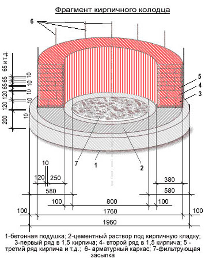
- For stone structures, the arrangement of a waterproofing bottom layer, as shown by the diagram or plan (layer of at least 20 cm), subsequent tamping.
All preparatory work has been completed and the next stage is installation.
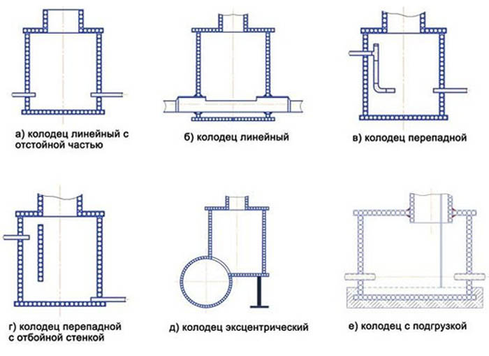
stone wells
The steps and actions are:
- Preparation of the base involves laying a slab or arranging a pillow made of M-50 concrete with a thickness of 100 mm;
- Arrangement of a concrete tray (M-100) reinforced with a steel mesh of the desired shape;
- Seal with concrete and bitumen end openings of the pipeline;
- Creation of an insulating layer of the internal cavity of the rings of the structure;
- The rings are installed only after the tray has gained strength (2-3 days), then the floor slab is laid. The solution used for work - M-50;
- Sealing joints with cement mixture;
- Waterproofing with bitumen;
- Mandatory plastering of the tray with cement, followed by ironing;
- Installation of clay interlocks at the entry point of a pipe/pipes with a width of at least 300 mm and a height of 600 mm greater than the diameter of the pipeline.
Subsequent test work takes place within a day and includes the complete filling of the structure with water with the blocking of the pipeline by temporary plugs. If leaks are not detected, the well walls are backfilled, a blind area measuring 1.5 m is equipped, the joints are insulated with a hot bituminous mixture - work on SNiP has been completed, the system can be put into operation.
The installation schemes for brick structures practically repeat the concrete ones, but instead of combining the rings, a stone is laid out. Waterproofing works are completely identical. Thus, stone wells of any type of sewerage are installed: household, industrial, storm water or drainage. But each design has its own nuances:
- The storm drain is equipped with lattice hatches that have a catchment function;
- Drainage wells themselves are drainage systems, so installation does not require special calculations.
Differences in configuration are determined by the series:
- KFK/KDK - household drains;
- KLV / KLK - storm water;
- KDV / KDN - drainage wells.
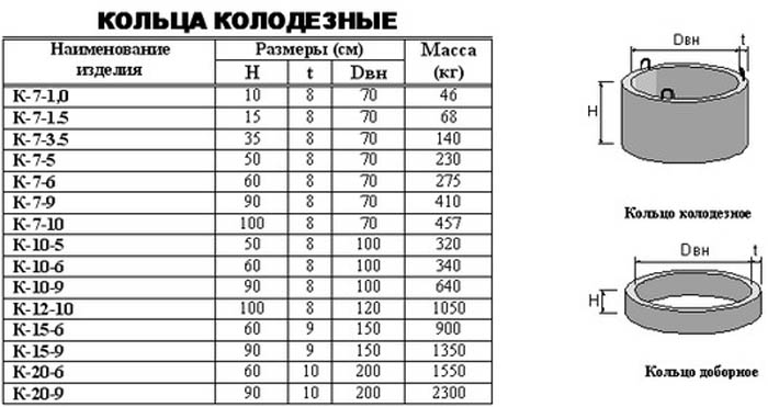
The size table gives a complete picture:
Drop wells
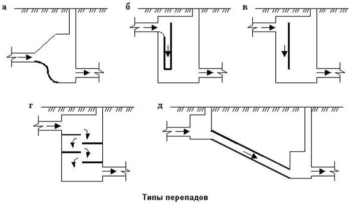
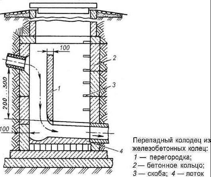
A more complex configuration determines the scope and requirements of SNiP for overflow wells. In addition to the tray device, it is necessary to make:
- Installation of risers;
- Have a water pumping equipment;
- Install a water wall;
- Create a practical profile;
- Set up a pit.
Otherwise, with regard to the installation of the shaft, base, floors - the rules are the same as the previous ones.
Important! The exception is a standing overflow well - a metal pipe is required to be installed in the base, which will prevent the destruction of the concrete structure.
The schema looks like this:
- Pipe-riser;
- Pillow water-breaking;
- Metal base (plate);
- Funnel reception (stand-up).
The funnel is required for compensatory discharge processes that are formed in the riser due to the rapid movement of flows. Do-it-yourself creation of overflow wells in private areas is not recommended, unless it is a pipeline with a diameter of 60 cm and a level difference of up to 3 m, but such pipes are practically not used in individual systems, successfully replaced by other types of wells.
The requirements of SNiP for drop wells are simple, installation is recommended in the following cases:
- It is necessary to significantly reduce the depth of the pipeline;
- If there are intersections with other underground utilities;
- Need to adjust the flow rate of wastewater;
- In the case when the well is the last before the direct discharge of wastewater into the river, lake.
The same reasons can serve as a reasonable justification for installing a drop well on your own site.
Arrangement of pipeline inlets into the well
Depending on the conditions of a particular place and soil, the entrance parts to the well are performed in different ways. Installation on dry ground is easier, as it regulates only two types of materials: cement and asbestos-cement mixture. For wet ground installation requires resin strand and waterproofing materials. But both methods are designed only for soils without subsidence.
On moving soils, SNiP installed movable connections: winding pipes with flexible plastic insulating packing. If you deviate from the rules, then you can insert a metal sleeve into the hole of the hatch and arrange a packing from a waterproofing material already inside.
polymer wells
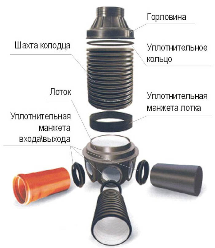
Being a fairly new alternative replacement for stone wells, plastic structures are successfully used to create structures, however, so far only in private households.
Installation is regulated not according to SNiP, but only in accordance with the specifications, so the installation does not require functional features. An important difference between the simplest wells of intra-yard networks is simplicity, a large volume of water passage and the strength of the material. In addition to other advantages, polymer structures can reduce the size, for example, a concrete well of 1 m can be replaced with a plastic one with a diameter of only 30 cm. Despite the small volumes, maintenance will be even much easier than a stone well.
There are plenty of other benefits too:
- Easy installation;
- Low costs for digging pits, pits - smaller sizes do not require large excavations;
- The outlets and tray design are clearly defined by the standards, are factory cast, and therefore there is no need for additional equipment or fabrication;
- The materials for the manufacture of wells are indicated above, polymer structures are combined with any pipes made of plastic, cement, asbestos.
That is why it is worth once again paying attention to the choice before starting the installation of a sewer manhole. All installation schemes are simple, SNiP clearly indicates installation requirements, tray sizes, recommended volumes. But at the same time, the owner will be able to save on related work, the purchase of equipment and time costs.
Summer cottages, where it is not necessary to equip many wells, to build a tray for each, it is more practical to equip them with polymer structures. Modest in size, they do not lose their functionality and practicality.