Electrical probe for checking voltage. Types of voltage indicator screwdrivers and rules for using them. Using Voltage Indicators
“CONTROL” and “DIALING” for ELECTRICIAN.
When checking the electrical circuit of a machine in noisy workshops, it is not entirely convenient to use measuring instruments; you have to simultaneously hold the probes of the device, look at its readings and also click the operating mode switch. And although the “RULES FOR SAFE OPERATION OF CONSUMER ELECTRICAL INSTALLATIONS” prohibit the use of test lamps, electricians often use a simple test lamp to check the serviceability of electrical circuits, which is used as a convenient and multifunctional “device.”
Although, in general, the point is not in the light bulb, but in the one who holds it - you can screw up both the voltage indicator and the certified device if it is in the hands of an irresponsible worker or someone who does not know how to handle it properly.
But the convenience of using the “control” correctly speaks for itself:
By the glow of the lamp, you can visually estimate the magnitude of the applied voltage;
The glow of an incandescent lamp is clearly visible in bright light;
Due to the low input resistance, it does not give false alarms from induced voltage (“crosstalk”) and “through the load”;
Allows you to check protective grounding circuits, the operation (or malfunction) of an RCD, and, among other things, can be used as a portable light source.
For safe use, the control lamp must be structurally enclosed in a case made of insulating material, transparent or with a slot for the passage of the light signal. Conductors must be flexible, reliably insulated, no more than 0.5 m long, to exclude the possibility of a short circuit when passing through a common input, exit the fittings into different holes, and have hard electrodes at the free ends, protected by insulated handles; the length of the bare end of the electrode should not exceed 10 - 20 mm.
To make a simple and easy-to-repeat version of the “control”: take two 220V 15W lamps for the refrigerator, solder them in series with each other, as conductors you can use multimeter probes with plastic holders at the ends, the wires in which it is advisable to replace with better ones. The flanges on these probes prevent the possibility of fingers getting into contact with the open ends of the probes and conductive parts of the installations. Then we place both lamps in a suitable case (for example, in a piece of transparent hose) and bring the wires out. 
In the process of checking the integrity of the wiring, you should strictly follow the electrical safety rules; the “control” should be suspended on the wires; when checking close to the floor, it should be moved as far away from you as possible.
TEST - INDICATOR.
In those cases (conditions) when it is more convenient to use a “control” rather than a device, that is, in simple diagrams for a preliminary assessment of the functioning of components during the repair and adjustment of electrical appliances and electronic devices, where measurement accuracy is not required. An indicator probe can often be useful to determine in the circuit being tested:
Availability of alternating or direct voltage from 12 to 400V,
Phase wire in alternating current circuits,
Approximate voltage value,
Polarity of DC circuits,
Perform continuity testing of circuits, including windings of electric motors, starters, transformers, contacts,
Check the serviceability of diodes, transistors, thyristors, etc.
These requirements are well met by various indicators with light and sound indications, which are simple and reliable in operation.
EASY TEST, equipped with two LEDs and a neon lamp, allows you to check the presence of a phase in the network, detect a short circuit and the presence of resistance in the circuit. With its help, you can check the coils of magnetic starters and relays for open circuits, ring the ends of chokes and motors, deal with the terminals of multi-winding transformers, check rectifier diodes and much more.
The probe is powered by a Krona battery or any other similar type with a voltage of 9V; the current consumption with the probes closed is no more than 110 mA; with the probes open, no energy is consumed, which allows you to do without a power switch and operating mode switch.
The functionality of the device is maintained when the supply voltage is reduced to 4V; when the battery is discharged (below 4V), it can work as an indicator of the mains voltage. 

When a circuit with a resistance of zero to 150 Ohms is tested, the red and yellow LEDs light up; with a circuit resistance of 150 Ohms to 50 kOhms, only the yellow LED lights up. When 220-380V mains voltage is applied to the probes, the neon lamp lights up and the LEDs flicker slightly.
The probe is made of three transistors; in the initial state, all transistors are closed, since the probe probes are open. When the probes are closed, a voltage of positive polarity is supplied through diode VD1 and resistor R5 to the gate of field-effect transistor V1, which opens and is connected through the base-emitter junction of transistor V3 to the negative wire of the power source. LED VD2 flashes. Transistor V3 also opens, LED VD4 lights up. When connected to resistance probes within the range of 150 Ohm-50 kOhm, the VD2 LED goes out, since it is shunted by resistor R2, the resistance of which is relatively less than that measured, and the voltage on it is not enough for it to glow. When mains voltage is applied to the probes, the neon lamp HL1 flashes.
A half-wave mains voltage rectifier is assembled using diode VD1. When the voltage on the zener diode VD3 (12V) is reached, transistor V2 opens and thereby closes field-effect transistor V1. LEDs flicker slightly.  DETAILS: Field-effect transistor TSF5N60M can be replaced with 2SK1365, 2SK1338 from pulse chargers of a video camera, etc. Transistors V2, V3 are replaceable with 13003A from an energy-saving lamp. Zener diode D814D, KS515A or similar with a stabilization voltage of 12-18V. Small-sized resistors 0.125 W. Neon lamp from a screwdriver indicator. Any LEDs, red or yellow. Any rectifier diode with a current of at least 0.3A and a reverse voltage of more than 600V, for example: 1N5399, KD281N.
When installed correctly, the probe begins to work immediately after power is applied. During setup, the range of 0-150 Ohms can be shifted in one direction or another by selecting resistor R2. The upper limit of the range 150 Ohm-50 kOhm depends on the instance of transistor V3.
The probe is placed in a suitable housing made of insulating material, such as the housing of a mobile phone charger. A probe pin comes out from the front, and a well-insulated wire with a pin (or crocodile) comes out from the end of the body.
UNIVERSAL INDICATOR ON THE CHIP.
Allows you to determine:
"Phase" wire in power circuits and electrical networks;
Availability of constant voltage in the range 10...120V;
Availability of alternating voltage in the range 10...240V;
Availability of signal in telephone networks;
Availability of a signal in the broadcast network;
Serviceability of fuses;
Serviceability of resistors with a resistance of 0... 100 kom;
Serviceability of capacitors with a capacity of 0.05...20 µF;
Serviceability of transitions of silicon diodes and transistors;
Availability of TTL and CMOS pulses up to 10 kHz.
In addition, you can find the ends of the wires in the wiring harness, both with the help of supply voltage and without it. 
Schematic diagram of the indicator.
When the probes are open, the voltage at pin 1 of element DD1.1 is determined by the voltage drop across the series-connected elements HL1, HL2, R3 and R4 is not enough to trigger trigger DD1.1. The multivibrator on DD1.1, DD1.2 does not work, the HL4 LED does not light up. In this mode, the current consumed from battery GB1 does not exceed 2...3 µA, which allows the indicator to do without a power switch.
In the “continuity” mode of the circuits, when the probes are closed, the input current of the circuit passes through resistors R1-R4, the voltage at pin 1 of element DD1.1 increases and triggers the multivibrator on elements DD1.1, DD1.2. From the multivibrator, pulses with an oscillation frequency of about 3 kHz are supplied to element DD1.3 - a buffer amplifier for the HL4 LED. In addition to the light indication of the operation of the multivibrator, the BF1 emitter also produces an audible alarm, which, to increase the signal amplitude, is connected between two inverters - DD1.4 and DD1.1.
Applying a constant voltage of 10... 120V to the input of the indicator causes the LEDs HL1, HL2 to glow, and with the polarity reversed to that indicated at the inputs, HL3. With increasing controlled voltage, the brightness of their glow, noticeable to the eye already at 10V, increases. When monitoring an alternating voltage indicator of 10... 120V with a frequency of 50 Hz, the glow of all LEDs HL1 -HL4 is visible, and by ear the presence of voltage with a frequency of 50 Hz is noticeable due to the characteristic tone modulation of 3 kHz. Moreover, auditory control appears to be more sensitive, since this modulation is already noticeable at voltages above 1.5V.
When a working oxide capacitor with a capacity of 20 μF is connected to the probes (in accordance with the polarity of the voltage on the probes), it is charged through the R1 - R4 circuit. In this case, the duration of the tone signal is proportional to the capacitance of the capacitor being tested - about 2 seconds per microfarad.
Checking the serviceability of semiconductor diodes and transistor junctions requires no explanation. True, the reverse current of the p-n junction of a diode or transistor of more than 2 μA can cause an audible alarm for any polarity of the semiconductor junction.
TTL and CMOS logical levels are displayed with inversion, i.e. a high level corresponds to the absence of lighting of the HL4 LED and a tone signal, and a low level corresponds to the inclusion of an LED and a tone signal.
The advantage of the indicator is that the test voltage on its probes, not exceeding 4.5V at a current of 3 µA, is safe even for field and microwave devices.
The use of two resistors R1 and R2 in the circuit increases the safety of working with the indicator; the values of these resistors (R1 and R2) are selected depending on the limit value supplied to the controlled voltage input. So, to control the input voltage up to 380V, with a current through the HL1-HL3 LEDs of about 10 mA, the resistance of resistors R1 and R2 should be increased to 20 kOhm!
When connecting to operating equipment, it must be taken into account that the internal resistance of the indicator is only 24 kOhm.
In the design, it is recommended to use HL2 - AL307A or similar LEDs with a red glow, and HL4 - with a red or yellow glow (for example, AL307D). HL1, HL3 - AL307G or similar green light. Resistors R1, R2 - MLT-2, the remaining resistors and capacitors - any small ones. 

BF1 - any piezoceramic emitter; three 1.5V alkaline “button” cells, used in calculators, key fobs, flashlights, etc., are used as the G1 battery.
The design and installation of elements largely depends on the housing used; it is possible to produce a particularly small-sized structure using a microcircuit and surface-mounted parts. 
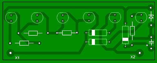
Drawing of a possible board option.
The board is designed for installation of MLT resistors and capacitors KM-6 (C1) and K10-17. LEDs are placed in a convenient place for observation on the front side of the case.
It is advisable to make the positive terminal of the input circuit of the device in the form of a probe, and the negative terminal in the form of a flexible wire with an alligator clip at the end.
If the parts are in good working order, adjustment of the device is usually not required. Current consumption with open inputs should not be more than 4 µA. If, when connecting the battery, the HL4 indicator lights up even when the terminals are open, you should select LEDs HL1, HL2 with a higher threshold voltage or HL3 with a lower reverse current of the p-n junction. You can increase the volume of the sound alarm by selecting resistor R6 or capacitor C1, adjusting the generator frequency closer to the frequency most efficiently emitted by the BF1 converter.
THE FOLLOWING DIAGRAM allows you to evaluate the magnitude and sign of the voltage ("+","-","~") within several limits: 36V, >36V, >110V, >220V, 380V, and you can also ring electrical circuits, contacts and relay coils, starters, incandescent lamps, p-n junctions, LEDs, etc., i.e. almost everything that an electrician most often encounters in the course of his work (with the exception of current measurement).

In the diagram, switches SA1 and SA2 are shown in the unpressed state, i.e. in the voltmeter position, the voltage value can be judged by the number of lit LEDs in the VD3...VD6 line, and the VD1 and VD2 LEDs show the polarity; the approximate (recommended) location of the elements on the front panel and in the case is shown in the figure. Resistor R2 must be made of two or three identical resistors connected in series, with a total resistance of 27...30 kOhm. Pressed switch SA2 turns the probe into a classic dialer, i.e. battery plus light bulb. If you press both switches SA1 and SA2, you can test circuits in two resistance ranges: - the first range - from 1 MOhm and above to ~1.5 kOhm (VD15 is lit); - second range - from 1 kOhm to 0 (VD15 and VD16 are lit). Zener diodes can be used in small-sized imported ones. Batteries (type "316") last a year or more.
The probe can be supplemented with a “phase” indicator (HL2, R8, contact E1), which will be very useful when repairing lighting.
Housing options depend on the dimensions of the parts used. It is better to place the switches on different sides of the board, then there will be fewer errors when using it at first. The most common error is that, without making sure that there is no voltage in any circuit, the user presses the switches to test, and the HL1 lamp burns out, acting in this case as a fuse. Thus, when working on open circuits, you must be careful and attentive, as required by safety regulations.
ELECTRICANT'S TEST.
Before you start working with the probe, the diagram of which is shown in the following figure, you need to charge the storage capacitor C1. To do this, simply insert the probe probes into the power outlet for a few seconds.
At the same time, the LEDs LED2 - LED6 light up, indicating that the probe is working and there is voltage in the network - 220V. 
During operation, the lighting of the LEDs indicates the presence of the following voltages:
LED4 - 36V;
LED3 - 110V;
LED2 - 220V;
LED1 - 380V.
LED5 is used for dialing (about a minute of continuous illumination), and LED6 indicates voltage polarity (when measuring voltage in DC circuits).
You need to pay attention to the fact that this is still a probe, not a measuring device, so the threshold for turning on the LEDs is not very clear, but quite sufficient. For example, at a voltage of 127V, LED4 and LED3 light up, and LED2 and LED1 are extinguished. It may be necessary to select resistances R1, R2 and R5 during setup for a more accurate indication.
The main elements of the probe are mounted on a printed circuit board; to reduce the thickness of the housing, VD1 and C1 are placed outside the board in the main body, where the circuit and indicators are located, and resistors R1 and R2 are in the auxiliary probe. When using a D816V zener diode, capacitor C1 must be designed for an operating voltage of at least 35V. With a high-quality capacitor, the charge remains for more than a day. The capacitor capacity can be increased. Diodes in the circuit - any with a maximum voltage above 50V.
UNIVERSAL TEST-INDICATOR.
The proposed device, consisting of an LED voltage scale, a unit for monitoring the conductivity of electrical circuits ("continuities"), an alternating voltage indicator and a phase wire indicator, is a good assistant when, during the repair and installation of electrical wiring, it becomes necessary to check the network voltage, determine the phase and neutral wires, " Ring the circuits for breaks or short circuits. 
The LED scale is made on LEDs LED2-LED6 and resistors R2-R6, shunting the LEDs, and has five gradations of standard voltages. The operation of the scale is based on the lighting of a certain LED when the voltage drop across its shunt resistor is about 1.7V. Circuit VD3, LED7 serves to indicate alternating voltage on the probe probes, as well as the reverse polarity of direct voltage compared to that indicated in the diagram.
The conductivity control unit consists of a storage capacitor of a relatively large capacity C1, its charging circuit VD1, VD2 and the indication circuit R7, LED1. When the probes are connected to a voltage source for a few seconds, the capacitor is charged through the diode VD1 from the voltage dropping across the zener diode VD2. The probe is ready to test the circuits.
If you touch the working circuit with the probes, the capacitor discharge current will flow through it, resistor R1, LED1 and resistor R7. The LED will light up. As the capacitor discharges, the brightness of the LED will decrease. The phase wire indicator is assembled according to the relaxation generator circuit, touching the E1 sensor with your finger, and touching the phase wire with the “+” probe. The voltage rectified by diodes VD4, VD5 charges capacitor C2. When the voltage across it reaches a certain value, the neon lamp HL1 will flash. The capacitor is discharged through it, the process is repeated.
It is advisable to select LEDs - indicated in the diagram or their foreign analogues, for example, L-63IT according to similar parameters, and LED1 - according to maximum luminous efficiency at low current. Instead of the BZY97(10V) zener diode indicated in the diagram, you can use D814B or KS168. Capacitor C1 - K50-35 or its foreign equivalent. Resistors R2-R9 - MLT of appropriate power, R1 - PEV, S5-37 with a power of at least 8W (you can install six MLT-2 resistors connected in series with a resistance of 1.3 kOhm).

The design can be made in the form of two probes made of dielectric material, connected to each other by a flexible wire in double insulation, designed for a voltage of at least 380V. The main probe, on which the indicators are located, and the auxiliary probe, which contains resistor R1. Operation in all modes is carried out without any switching and without an internal battery. The probes have pointed tips with a diameter of 3 and a length of 20 mm.
If all parts are in working order and installed correctly, the probe can be used immediately. You may have to select resistor R7 in order to achieve clear lighting of LED1 (when connecting a resistor with a resistance of 300...400 Ohms between the probes). But its resistance should not be significantly reduced, since this will cause a rapid discharge of the storage capacitor. And to achieve clearly visible flashes of a neon lamp, it is enough to select resistor R8.
When it is often necessary to monitor the performance and repair various devices where constant and alternating voltages of different values (36v, 100v, 220v and 380v) are used, the proposed probe is very convenient, since there is no need to switch at different controlled voltages. A VARIANT of such a probe on two-color LEDs, which, in addition to “testing” the circuits, allows you to visually determine the type of direct or alternating voltage and approximately estimate its value in the range from 12 to 380V, is presented in the following figure. 
The circuit contains a scale of two-color LEDs LED1-LED5, a phase wire indicator on a neon lamp HL1 and a “continuity indicator” - an indicator of the conductivity of the electrical circuit.
To use the device as a “dialing”, you must first charge the storage capacitor C1. To do this, the input of the device is connected for 15...20 s to a 220V network or to a constant voltage source of 12V or more (plus to plug Xp1). During this time, capacitor C1 manages to charge through the diode VD2 to a voltage slightly less than 5V (it is limited by the zener diode VD1 ). Upon subsequent connection to the controlled circuit, if it is working properly, the capacitor will be discharged through it, resistor R7 and LED6, which will light up. If the test is carried out briefly, then charging the capacitor will be enough for several tests, after which the charging of the capacitor should be repeated. To indicate voltage, the device input - pin Xp1 and Xp2 (using a flexible insulated wire) is connected to the controlled points. Depending on the potential difference between these points, different current flows through resistors R1-R6 and the zener diode VD1. As the input voltage increases, the current also increases, which leads to an increase in the voltage across resistors R2-R6. LEDs LED1-LED5 light up alternately, signaling the value of the input voltage. The values of resistors R2-R6 are selected so that the LEDs light up at voltage:
LED1 - 12V or more,
LED2 - 36V or more,
LED3 - 127V or more,
LED4 - 220V or more,
LED5 - 380V or more.
Depending on the polarity of the input voltage, the color of the glow will be different. If pin Xp1 is plus relative to socket Xs1. The LEDs light up red, if negative - green. With variable input voltage, the glow color is yellow. It should be noted that with an alternating or negative input voltage, LED6 may also light up.
In the phase wire indicator mode in the network, any of the inputs (Xp1 or Xp2) is connected to the controlled circuit and touch the E1 sensor with your finger; if this circuit is connected to the phase wire, the neon indicator lamp lights up.
The circuit uses: fixed resistors R1 - PEV-10. the rest are MLT, S2-23. capacitor - K50-35 or imported, diode KD102B can be replaced with any diode from the 1N400x series, zener diode KS147A - with KS156A, instead of two-color LEDs, you can use two different colors of light, turning them on back-to-back, it is advisable to use LED6 LED with increased brightness .
It should be noted that LEDs of different glow colors have different forward voltage values, so their switching thresholds at different input voltage polarities will not be the same.
LED1-LED5 and neon lamp HL1 are placed in a row so that they are clearly visible. Probe Xp1 - a metal pin, pointed at the end, is placed at the end of the housing, Xp2 - an auxiliary probe in which resistor R1 is located, connected to the main body with a flexible wire with good insulation. As an E1 sensor, you can use a screw located on the device body.
CONTINUITY TEST - VOLTAGE INDICATOR.
A rather convenient device that can be used to check the integrity of lines and the presence of both direct and alternating voltage, which can provide useful assistance to an electrician in his work. The circuit is a direct current amplifier using transistors VT1, VT2 with base currents limited by resistors R1-R3. Capacitor C1 creates a negative feedback circuit for alternating current, eliminating false indications from external noise. Resistor R4 in the VT2 base circuit serves to set the required resistance measurement limit, R2 limits the current when the probe operates in AC and DC circuits. Diode VD1 rectifies alternating current. 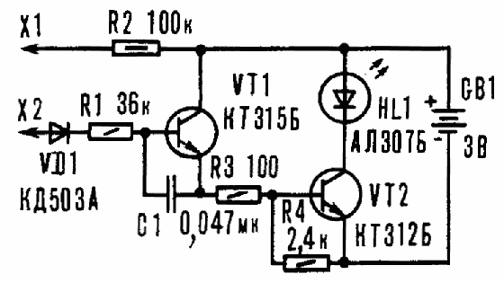

In the initial state, the transistors are closed and the HL1 LED does not light up, but if the probes of the device are connected together or connected to a working electrical circuit with a resistance of no more than 500 kOhm, the LED lights up. The brightness of its glow depends on the resistance of the circuit being tested - the higher it is, the lower the brightness.
When the probe is connected to an AC circuit, the positive half-waves open the transistors and the LED lights up. If the voltage is constant, the LED will light up when there is a “plus” of the source on the X2 probe.
The device can use silicon transistors of the KT312, KT315 series with any letter index, with a P21e value from 20 to 50. You can also use pnp transistors by changing the polarity of the diodes and the power supply. It is better to install a silicon diode VD1 KD503A or similar. LED type AL102, AL307 with ignition voltage 2-2.6V. Resistors MLT-0.125, MLT-0.25, MLT-0.5. Capacitor - K10-7V, K73 or any other small-sized one. The device is powered by two A332 elements.
It is better to configure the device on a temporary circuit board, excluding resistor R4 from the circuit. Connect a resistor with a resistance of about 500 kOhm to the probes to set the upper limit of resistance measurement, and the LED should light up. If this does not happen, the transistors need to be replaced with others with a higher coefficient h21e. After the LED lights up, select the value of R4 to achieve a minimum glow at the selected limit. If necessary, you can enter other resistance measurement limits into the device by changing them using a switch. Probe X2 is fixed to the body, and X1 is connected to the device with a stranded wire, the latter can be made from a collet pencil or used ready-made from an avometer.
ABOUT OPERATING THE DEVICE. The serviceability of diodes and transistors is checked by comparing the resistances of p-n junctions. The absence of a glow indicates a break in the transition, and if it is constant, the transition is broken. When a working capacitor is connected to the probe, the LED flashes and then goes off. Otherwise, when the capacitor is broken or has a large leak, the LED lights up constantly. Thus, it is possible to test capacitors with ratings of 4700 pF and higher, and the duration of the flashes depends on the measured capacitance - the larger it is, the longer the LED burns.
When checking electrical circuits, the LED will light up only in cases where they have a resistance of less than 500 kOhm. If this value is exceeded, the LED will not light up.
The presence of alternating voltage is determined by the glow of the LED. At constant voltage, the LED lights up only when there is a “plus” of the voltage source on probe X2.
The phase wire is determined as follows: probe XI is taken in the hand, and probe X2 is touched to the wire, and if the LED lights up, then this is the phase wire of the network. Unlike the indicator on the neon, there are no false positives from external interference.
Performing phasing is also not difficult. If the LED lights up when the probe touches current-carrying wires, it means that the probes are on different phases of the network, and if there is no light, they are on the same phase.
The insulation resistance of electrical appliances is checked in this way. One probe touches the wire, and the other touches the body of the electrical appliance. If the LED lights up, then the insulation resistance is below normal. The absence of a glow indicates that the device is working properly. 
A slightly modified version of the previous circuit, which works as follows: When dialing: if the probes are connected to each other, the green LED will light up (with these circuit ratings, circuits with a resistance of up to 200 kOhm “ring”).
If there is voltage in the circuit, both green and red LEDs light up together: the probe works as an indicator of constant voltage from 5V to 48V and alternating voltage up to 380V, the brightness of the red LED depends on the voltage in the circuit being tested, i.e. at 220V the brightness will be higher than at 12V. This device runs on two batteries (tablets), maintaining functionality for several years.
UNIVERSAL TEST significantly facilitates troubleshooting when repairing various radio equipment; it can be used to check the electrical circuit and its individual elements (diodes, transistors, capacitors, resistors). It will help verify the presence of direct or alternating voltage from 1 to 400V, determine the phase and neutral wires, check for open circuits and short circuits in the windings of electric motors, transformers, chokes, relays, magnetic starters, and inductors.
In addition, the probe allows you to check the passage of a signal in the LF, IF, HF paths of radios, televisions, amplifiers, etc., it is economical, it operates from two elements with a voltage of 1.5V. 
Universal probe circuit.
The device is made of nine transistors and consists of a measuring generator using transistors VT1, VT2, the operating frequency of which is determined by the parameters of capacitor C1 and the inductor being tested. Variable resistor R1 sets the depth of positive feedback, ensuring reliable operation of the generator.
Transistor VT3, operating in diode mode, creates the necessary voltage level shift between the emitter of transistor VT2 and the base of VT5. A pulse generator is assembled on transistors VT5, VT6, which, together with a power amplifier on transistor VT7, ensures the operation of the HL1 LED in one of three modes: no light, blinking and continuous light. The operating mode of the pulse generator is determined by the bias voltage based on transistor VT5.
The VT4 transistor is used as a direct current amplifier, which is used to check the resistance and presence of voltage. The circuit on transistors VT8, VT9 is a trigger multivibrator with an operating frequency of about 1 kHz. The signal contains many harmonics, so it can be used to test not only LF stages, but also IF and HF stages.
In addition to those indicated in the diagram, transistors VT1, VT2, VT4, VT7 can be of types KT312, KT315, KT358, KT3102. Transistors KT3107V can be replaced by any of KT361, KT3107, KT502. Transistor VT3 must be from the KT315 series. It is advisable to use variable resistor R1 with a logarithmic characteristic “B” or “C”. The flattest part of the characteristic should appear when the engine is in the right position according to the diagram. Power source – two galvanic elements of AA size with a voltage of 1.5V.
The board and batteries are placed in a plastic case of suitable dimensions. A variable resistor R1, switches SA1–SA3 and an LED HL1 are installed on the top cover.
A probe that is correctly assembled and made from serviceable parts begins to work immediately after the supply voltage is applied. If in the extreme right position of the slider of resistor R1 and with probes X1, X2 open, the LED lights up, then you need to select resistor R4 (increase its resistance) so that the LED goes out.
When checking voltage, resistance up to 500 kOhm, serviceability of transistors, diodes, capacitors with a capacity of 5 nF...10 μF and determining the phase wire, switch SA1 is set to the “Probe” position, and SA2 to position “1”. The presence of alternating voltage is determined by the glow of the LED. At a constant voltage of 1...400V, the LED lights up only when there is a “plus” of the voltage source on the X1 probe. The serviceability of diodes and transistors is checked by comparing the resistances of p-n junctions. If the LED does not light up, the transition is broken. If it is constant, then the transition is broken. When a working capacitor is connected to the probe, the LED flashes and then goes off. If the capacitor is broken or has a large leak, the LED lights up constantly. Moreover, the duration of the flashes depends on the measured capacitance: the larger it is, the longer the LED glows, and vice versa. The phase wire is determined as follows: probe X2 is taken in the hand, and probe X1 is touched to the wire. If the LED lights up, then this is the phase wire of the network.
When testing inductors of 200 µH...2 H and capacitors with a capacity of 10...2000 µF, switch SA1 is set to the “Probe” position, and SA2 is set to position “2”. When a working inductor is connected and the R1 slider is set to a certain position, the LED blinks. If there is a short circuit of turns in the winding being tested, the LED lights up; If there is a break in the winding, the LED does not light. Checking capacitors with a capacity of 10...2000 μF is similar to the check described above.
When using the probe as a signal generator, switch SA1 is set to the “Generator” position. Probe X2 is connected to the ground of the device being tested, and probe X1 is connected to the corresponding point in the circuit. If you connect an earphone, for example, TM72A, in series with probe X1, you can perform an audio “test” of electrical circuits.
It should be noted that when testing the windings of transformers with a high transformation ratio, the probe should be connected to the winding with the largest number of turns.
SIMPLE TEST-INDICATOR.
Despite the abundance and accessibility of digital measuring instruments (multimeters), radio amateurs often use simpler indicator devices called probes to check the presence of voltage and the serviceability of various circuits and elements. Using this probe, you can check the presence of voltage in the controlled circuit, determine its type (constant or alternating), and also test the circuits for serviceability. 
The device diagram is shown in Fig. 1 LED HL2 indicates the presence of a constant voltage of a certain polarity at the input (plugs XP1 and XP2). If positive voltage is supplied to plug XP1, and negative voltage is supplied to XP2, current flows through current-limiting resistor R2, protective diode VD2, zener diode VD3 and LED HL2, so LED HL2 will light. Moreover, the brightness of its glow depends on the input voltage. If the polarity of the input voltage is reversed, it will not glow.
The HL1 LED indicates the presence of alternating voltage at the input of the device. It is connected through current-limiting capacitor C1 and resistor R3, diode VD1 protects this LED from the negative half-wave of alternating voltage. Simultaneously with LED HL1, HL2 will also light. Resistor R1 serves to discharge capacitor C1. The minimum indicated voltage is 8V.
A high-capacity ionistor C2 is used as a source of constant voltage for the “continuity” mode of connecting wires. It must be charged before testing. To do this, connect the device to a 220V network for about fifteen minutes. The ionistor is charged through elements R2, VD2, HL2, the voltage on it is limited by the zener diode VD3. After this, the device input is connected to the circuit being tested and the SB1 button is pressed. If the wire is working properly, current will flow through it, the contacts of this button, LED HL3, resistors R4, R5 and fuse-link FU1 and LED HL3 will light up, signaling this. The energy reserve in the ionistor is enough to continuously illuminate this LED for about 20 minutes.
The limiting diode VD4 (limiting voltage does not exceed 10.5V) together with the fuse-link FU1 protects the capacitor from high voltage if the SB1 button is accidentally pressed while monitoring the input voltage or charging the capacitor. The fuse link will burn out and will need to be replaced.
The device uses resistors MLT, C2-23, capacitor C1 - K73-17v, diodes I N4007 can be replaced with diodes 1N4004, 1N4005, 1 N4006, zener diode 1N4733 - with 1N5338B. All parts are mounted on a prototype circuit board using wire wiring.
CALL FROM TELEPHONE CAPSULE.
If someone has a TK-67-NT telephone capsule (earphone) lying around at home, designed to work in telephone sets, or a similar one with a metal membrane and having two coils inside connected in series, then on its basis you can assemble a simple audio “dialer”. 
True, for this the earphone will have to be modified a little - disassemble and disconnect the coils, making the leads from each of them free. All parts can be placed inside the telephone capsule under the membrane near the coils. After assembly, the phone will turn into an excellent sound generator, which can be used, for example, to check printed circuit boards for short circuits or for other purposes - say, as a sound indicator of turns.

Scheme options are shown in the figure.
The basis of the probe is a generator with inductive feedback, assembled on a transistor VT1 and a telephone BF1. In the diagram above, the supply voltage (battery) is indicated as 3V, but it can be changed (from 3 to 12V) by selecting the current-limiting resistor R1. Almost any low-power (preferably germanium) transistor can be used as VT1. If you have a transistor with N-P-N conductivity at hand, then it will work, but you will have to change the polarity of the power source. If the generator does not start the first time you turn it on, you need to swap the leads of one of the coils. For greater sound volume, the frequency of the generator must be chosen close to the resonant frequency of the phone; this can be done by changing the gap between the membrane and the core.
When working with a 220 Volt electrical network, you have to make some measurements.
First of all, this is a check for the presence of voltage, and in this case we are interested in the result - there is voltage or not.
When checking wires, switches, etc. you need a dialing device. In this case, the result is also satisfactory - there is a chain, there is no chain.
When checking the integrity of light bulbs and other electrical appliances, it is also enough to ring the circuit to make sure there is no break. Therefore, the tester is inconvenient and not needed at all for working with electrical wiring. Needed universal probe to check the presence of voltage and to test circuits with load assessment - a circuit with zero resistance (wire) or a circuit with a load.
The scheme of such electrician tester is presented in Fig. 1.
In the initial state, when nothing is pressed, the probe operates in the mode of a two-pole voltage indicator.
The voltage is estimated by the glow of two red LEDs HL1, HL2 and a neon light bulb La1. Up to a voltage of 100 volts, only the LEDs light up, and by the brightness of the glow you can roughly estimate the voltage value. The LEDs begin to glow at a voltage of about 2 Volts. With alternating current, both LEDs light up, with constant current, only one of the two. You can determine the polarity of the voltage by marking both LEDs with plus and minus signs.
When the voltage is more than 100 volts, a neon light comes on in addition to the LEDs. You can see it very clearly right away - all the indicators are shining - so be careful.
To search for a phase, an additional circuit of a single-pole voltage indicator is built into the probe.
To determine the phase wire, you need to touch the contact of the indicator (without touching the clamp - it must be in the transport position) and touch the wires being tested with a probe. The glow of the neon indicator indicates the presence of voltage on the phase wire.
To test the circuit, press and hold the S1 button.  In the first mode, continuity testing is carried out through an LED with a limiting resistor. Power is supplied by two finger or little finger batteries. The HL3 LED will light up when the resistance of the dialed circuit increases to almost 10 kOhm. The disadvantage of the LED indicator is that it does not distinguish a completely short-circuited circuit from a large load (300 W and above) - the glow of the indicator due to the equalizing effect of the ballast resistor R3 is almost the same.
For evaluating shorted circuits, fuses, wires, etc. switch the probe (S2) to low resistance mode. Now a regular light bulb from a 2.5 V flashlight operates through the battery circuit. The resistance of the light bulb is low, the current through it is 0.15 Ampere, so the presence of any slight circuit resistance of more than 5 Ohms will cause the light bulb to go out. Therefore, this mode is excellent for identifying wires. The device fits very well in a long plastic case, like a toothbrush case. It is convenient to make the probe of the device folding, then you can carry it in your pocket.
The device can be significantly simplified by leaving only an LED indicator without neon and only LED dialing. The information content, of course, immediately decreases.  The simplified probe circuit is shown in Fig. 4. It is good to have such a probe as part of a small tool kit - it takes up little space.
  When an electrician and a control engineer works in industrial electrical installations, the set of functions even for a universal probe according to the scheme in Fig. 1 is a little not enough. You always have to take a tester with you to measure, for example, phase imbalance or the resistance of the motor windings in order to identify its damage. By the way, the presence of short-circuited turns, if there are only a few of them, cannot be determined even with a digital multimeter, and the engine will heat up.
There is a method for determining short-circuited turns in electric motors, transformers, chokes and other coils with high inductance. Evaluate the occurrence of self-inductive emf when turning off the current through the inductance.
In the presence of high inductance and quality factor, the self-inductive emf that occurs at the ends of the coil when the current is turned off is several tens or even hundreds of times higher than the supplied voltage. If at this moment a neon light bulb is connected to the ends of the coil, it will flash brightly. Naturally, the light bulb must be protected by a limiting resistor.
A separate diagram of such a probe is shown in Fig. 2.  When the power is turned on with toggle switch S1, the connected inductance is powered from the power source. The current in this circuit is limited only by the inductance resistance and the internal resistance of the source.
A light bulb (or LED) serves as an indicator that the current is turned on. The neon indicator is connected in parallel to the coil through a limiting resistor. When you press button S2, the current through the coil is turned off. At this moment, a neon light flashes briefly.
If there are short-circuited turns in the coil, its quality factor drops tens of times, and the neon light bulb no longer flashes.
Carrying a large number of devices with you when working in electrical installations is inconvenient. Moreover, it is convenient and safe to work in large and deep electrical panels when your hands are at some distance from live parts. This is exactly what a probe with a long plastic body and a long insulated probe provides.
So I decided to collect super universal electrician's probe, which includes almost all the functions necessary for this job.
The resulting diagram is presented in Fig. 3.  A two-pole switch S3 is introduced into the probe circuit according to Fig. 1, which turns the probe into the mode for determining the self-induction EMF. To turn on the current through the inductance, use the S4 button; when pressed, it connects the power source, and when released, it breaks the circuit.
This is done in order not to put too much strain on the batteries - if not handled carefully, they can quickly run out. The indicator for turning on the current through the coil is the standard La2 continuity light or the HL3 LED. For short circuit protection, fuse F1 is installed. To increase the sensitivity of the neon indicator, another resistor is connected in parallel with R1.
The circuit of a two-pole indicator on a neon lamp La1 with resistor R1 is connected immediately at the input of the device. This is necessary both to determine the self-induction EMF and eliminates the influence of switches when checking for the presence of high voltage.
Additionally, a very useful flashlight function turned out to be a very useful one. When you press button S4, the incandescent lamp or LED lights up.  A super-small M818 multimeter is connected in parallel to the input circuits, which is attached to the bottom side of the probe for convenience. If it is necessary to make accurate measurements, it is switched on in the initial state of the probe. The connection is made with the same probes, readings are taken using the device. The indication circuits do not introduce errors into measurements even when measuring resistances.
  The device is mounted in a plastic non-conductive housing. The central probe is foldable and insulated with a PVC tube. The alligator clip is removable for easy measurements in sockets. To wind the wire, special brackets are made from polyethylene insulating caps. To secure the side probe using a crocodile, a separate self-tapping screw is screwed in, and the length of the wire is measured so that the side probe is fixed in this position.
This provides the necessary convenience when carrying the sample - it can be placed in any bag or pocket without damaging the pocket.
Many years of using such a probe have revealed its excellent effectiveness in any work with any electrical equipment.
Indispensable when setting up and repairing electric drive control panels, during installation and repair of electrical wiring, even when repairing electrical equipment of cars.
Working with live electrical installations and cable and wire products carries a risk of electrical injury. The reason for this is trivial - the directed movement of charged particles along a conductor cannot be seen with the naked eye. Therefore, during installation, routine maintenance and repair of electrical equipment, a voltage tester must be used.
Capable of at least simply showing the presence of potential, even without measuring its actual value.
A vital necessity
A voltage tester is a portable electrical device designed to indicate the presence of potential in conductive areas. In electrical networks, not all wires pose a danger when touched. Those with a phase present are subject to electric shock, but the neutral or ground wire is safe. True, there are reservations.
To understand why you might need a voltage tester at home, it’s easiest to give a number of examples. Let's imagine that there is a need for a grinder (grinder), which was temporarily provided by a neighbor. Models whose body is made of metal are still used. How to check that the internal circuits are intact and there is no voltage on the shell? Working with such a tool without first checking it is a very risky undertaking. Or, for example, you need to change a burnt-out light bulb in a lamp, the glass bulb of which has fallen, and only the base remains in the socket. Should you trust the electricians who did the wiring that the switch really breaks the phase wire, and not the neutral wire, and boldly unscrew the base? Doubtful! There are many similar examples. Having your own voltage tester, you can always quickly check an area of the electrical installation. In addition, more complex models allow the measurement of the effective value.
Basic Features
To check the presence of potential (phase), there is no need to spend money on purchasing an expensive device.

The simplest voltage tester is an indicator screwdriver. Inside its transparent body there is a small light bulb that lights up when the tip touches the area under potential.
How to check voltage with a tester? There is a special metal “penny” on the upper side of the dielectric handle. To check a section of the circuit, you need to touch the tip of the screwdriver to the conductor being tested, and touch the “penny” with your finger. The sting itself cannot be touched. If the phase is present, the light inside the screwdriver will light up. The second name for such screwdrivers is probes. They are designed for voltages up to 250 V.
It is not recommended to buy the cheapest models, since in the event of a breakdown of the internal resistor or an error in the circuit, you can get More advanced solutions do not require direct contact with a section of the circuit. The tip of such a screwdriver just needs to be held over the conductor. Designed for voltages up to 600 V.

In addition, some models are equipped with a display showing the current value.
There are modifications that do not require touching the “penny” with your finger. You can purchase a voltage tester without any problems. The instructions for it must be read. This will not only protect the device from damage, but will also protect the person himself.
Twin screwdriver
At the same time, the tool described above is too narrowly specialized. If, for example, it is required to perform the simplest task - phasing, then it turns out to be useless due to the presence of only one pole. In this case, you should pay attention to a more advanced tester - a dual low voltage indicator. Structurally, it can be compared to two screwdrivers connected by a wire. The maximum permissible voltage is 1 kV. Cost - from 100 rubles.
Let's look at how to measure voltage with a tester of this class. With the sting-electrode of one part you need to touch the section of the circuit being tested, and with the other - to the “ground”. This can be any grounded conductor, since dangerous potential does not flow through the device.

If the light inside the housing lights up, this will mean that there is voltage in the area. If it is necessary to perform phasing, you need to touch one phase wire with one probe, and the other with the other. If the phase on the wires is the same, then there will be no indication. Simpler models show the very fact of the presence of a phase, while more complex ones contain several LEDs on one of the handles, by the glow of which you can determine the voltage value.
Indicator
The next class of similar devices are the most famous models of the Ukrainian manufacturer “Contact”. Their cost starts from 400 rubles. Structurally, such testers are vaguely reminiscent of double screwdrivers, but have more advanced capabilities.

In particular, they can be used to determine the presence of a phase, approximately estimate the voltage level by the glow of LEDs, and check the conductor for integrity. There is a capacitor inside, which must be pre-charged by touching the probes to 220/380V for 20-30 s.
How to find a phase wire
Let's look at how to check the voltage with a tester. One of the probes of the device needs to touch the area of the electrical installation being tested, and with your finger - the Ph electrode on the body. If the corresponding LED lights up, then this conductor is energized. True, there is one nuance that is very well known to people who know how to work with a voltage tester of this type. It lies in the fact that checking the phase through Ph is not always correct, since the readings can be affected by interference from nearby current-carrying conductors. Let us explain: there are two adjacent wires, one of which is energized and the other is de-energized. If you do not know how to operate a voltage tester in detail, then when you check both conductors by touching them and the Ph electrode, it will turn out that according to the indication they are both phase.

However, it is not. It’s just that in a de-energized state, an EMF is induced under the influence of It reaches only a few tens of volts, but is detected by the device and is not a malfunction in its operation. In such cases, if doubt arises, you need to do something differently: touch the area being tested with one probe, and touch a known grounded point with the other. If there is a phase on the conductor, the LEDs will light up and show an approximate value of 220 V. By the way, having access to three-phase voltage, you can check the section by touching not only the “ground”, but also other phase wires. That is, the actions are similar to performing phasing. If there is voltage in the area, touching the opposite phase will cause the 380 V LEDs to light up.
Features of working with a pointer tester
The specification says that the current flowing through the circuits of the device when checking a potential of 220 V is no more than 10 mA. That is, if you touch one of the probes to a section of the electrical installation that is energized, the ammeter connected to the other probe will show the above current value.

Theoretically, this is a dangerous value (100 mA is lethal), but in practice, touching it with your hand is possible, however, as long as the internal circuits of the device are working properly.
Preparing to work with Contact
All solutions in which two blocks are connected by wire are potentially dangerous. One of their disadvantages is the possibility of damage to the connecting conductor while the shell is apparently intact. Therefore, when checking the presence of phase through Ph, it is recommended to use the probe of the block on which this electrode is located. In this case, the LED will work even if the wire is damaged. However, before taking measurements, you need to connect the device to the network and hold it for 20 s - during this time the internal energy source will charge. After this, you need to connect the probes together. If the wire is intact, the “test” LED will light up.
Universal tool
In addition to all the devices listed, there is another type - multimeters. Perhaps this is the most advanced voltage tester. We will now tell you how to use it. The cost of the most affordable models starts from 300 rubles. The operating procedure is described in the accompanying instructions, which you should read. If we talk about checking the voltage, then one wire needs to be connected to the COM connector, the other to V. Then set the switch to AC 750 mode (alternating current, limit 750 V) and touch the probes to the “ground” and the area being tested.
conclusions
During various repair and electrical installation operations, situations often arise related to the need to determine the presence of voltage in individual sections of the electrical circuit. In addition, there are often cases when you need to quickly verify the presence or absence of contact between various elements of the circuits under study. In all such cases, the most suitable tool for the job is indicator devices, grouped into a group of devices under the general name of an electrician's probe.
This concept includes a number of devices and instruments of the following names:
- so-called phase indicators or, more simply put, indicator screwdrivers;
- bipolar voltage indicators;
- universal probes;
- control devices (type “Arkashka”).
It should also be noted that most of the devices listed in the list do not, as a rule, take up much space in the repair kit. Some of their samples are generally carried directly in the pockets of work equipment, where they are, figuratively speaking, “always at hand.” The last statement especially applies to such well-known devices as an indicator screwdriver and a homemade control device. It should be especially emphasized that all these devices are quite reliable and easy to use and are a good replacement (supplement) for a relatively large and not always easy-to-use tester. With their help you can always deal with it.
Working with the Arkashka device is very simple.
Phase indicators
The phase indicator is usually made in the form of a small screwdriver, which, if necessary, acts as a probe.
The electrical circuit of this type of electrical tester consists of two elements connected in series - a neon light bulb and a resistor with a very low conductivity. In the process of checking the circuit for voltage, the operator needs to touch a special metal contact located on the top of the screwdriver with any finger. Thus, for the indicator to work successfully, the body of the person performing the operation must also be included in the circuit under study. A built-in high-resistance resistor, which plays the role of a voltage limiter in the measuring circuit, reduces the current flowing through it (including through a person) to an absolutely safe value (usually less than 0.3 mA).
Some features of working with an indicator screwdriver require separate explanations, consisting of the following:
Since the operator’s body is also involved in the process of electrical measurements, it is necessary to have reliable human contact with the ground and the screwdriver, which can only be done if there are no insulators in the working circuit (rubber mats and stands, as well as rubber gloves).
The phase indicator is capable of determining only the presence or absence of potential at the test point, which in no way indicates the presence of voltage in the measured circuit. If the neutral wire breaks, for example, there is no voltage in the network, but the probe will nevertheless indicate the presence of a “phase” on one of the contacts. In the case when you need to make sure that there is voltage, measurements should be carried out using a multimeter (ampere-voltmeter or tester).
If the measuring circuit of the indicator malfunctions (if a neon light bulb fails, for example), the latter will show you the absence of voltage at the test point. To avoid serious troubles, be sure to check the functionality of the indicator screwdriver by checking it in a circuit that is known to be energized.
You should be very careful when working with the indicator in bright sunlight, in which the glow of a neon light bulb is almost invisible to the eye, which can also lead to an error in determining the presence of a phase.
The simplest measuring instruments

The concept of “universal electrical probe” also includes a whole group of measuring instruments used, as a rule, to “test” the circuit under test, or, more simply, to determine its integrity.
A more advanced type of device in terms of its functionality is the PIN-90 bipolar voltage indicator, which allows you to determine the presence or absence of voltage between , as well as between the control point and ground. It differs from a conventional phase indicator in that it has another probe, which is connected to the main unit via a special cord and allows you to determine the presence of voltage in the circuit. Bipolar indicators of the ELIN-1SZ IP type are even more functional, equipped with two built-in LED indicators that allow you to record different voltage levels in the network.
Currently, many versions of universal testers for electrical work have been developed, both foreign and domestic (this includes various home-made devices). Such devices are distinguished by quite wide capabilities and allow performing various operations and are capable of:
- determine the presence, type and polarity of the voltage being tested;
- detect an open circuit;
- evaluate the resistance of this circuit;
- check capacitors of a certain capacity for breaks and leakage current;
- check semiconductor devices;
- monitor the status of the built-in batteries.

The figure shows an electrical diagram of the Raton device, which allows you to control the main of the previously listed quantities. Lack of power supply and versatility are the big advantages of this product.
In any technology, LEDs are used to display operating modes. The reasons are obvious - low cost, ultra-low power consumption, high reliability. Since the indicator circuits are very simple, there is no need to purchase factory-made products.
From the abundance of circuits for making a voltage indicator on LEDs with your own hands, you can choose the most optimal option. The indicator can be assembled in a couple of minutes from the most common radioelements.
All such circuits are divided into voltage indicators and current indicators according to their intended purpose.
Working with a 220V network
Let's consider the simplest option - phase checking.
This circuit is a current indicator light found on some screwdrivers. Such a device does not even require external power, since the potential difference between the phase wire and the air or hand is sufficient for the diode to glow.
To display the mains voltage, for example, to check the presence of current in the socket connector, the circuit is even simpler.

The simplest current indicator on 220V LEDs is assembled using capacitance to limit the current of the LED and a diode to protect against reverse half-wave.
DC Voltage Check
Often there is a need to ring the low-voltage circuit of household appliances, or check the integrity of a connection, for example, a wire from headphones.

As a current limiter, you can use a low-power incandescent lamp or a 50-100 Ohm resistor. Depending on the polarity of the connection, the corresponding diode lights up. This option is suitable for circuits up to 12V. For higher voltages, you will need to increase the limiting resistor.
Indicator for microcircuits (logic probe)

If there is a need to check the performance of a microcircuit, a simple probe with three stable states will help with this. If there is no signal (open circuit), the diodes do not light up. If there is a logical zero on the contact, a voltage of about 0.5 V appears, which opens transistor T1; if there is a logical one (about 2.4 V), transistor T2 opens.
This selectivity is achieved thanks to the different parameters of the transistors used. For KT315B the opening voltage is 0.4-0.5V, for KT203B it is 1V. If necessary, you can replace the transistors with others with similar parameters.