Side scan. Cone development. Constructing a cone scan. General concepts about surface development
Cylinder (straight circular cylinder) is a body consisting of two circles (the bases of a cylinder), combined by parallel translation, and all the segments connecting the corresponding points of these circles during parallel translation. The segments connecting the corresponding points of the base circles are called generators of the cylinder.
Here's another definition:
Cylinder- a body that is limited by a cylindrical surface with a closed guide and two parallel planes intersecting the generatrices of this surface.
Cylindrical surface- a surface that is formed by the movement of a straight line along a certain curve. The straight line is called the generatrix of the cylindrical surface, and the curved line is called the guide of the cylindrical surface.
Lateral surface of the cylinder- part of a cylindrical surface that is limited by parallel planes.
Cylinder bases- parts of parallel planes cut off by the side surface of the cylinder.
Fig.1 mini
The cylinder is called direct(Cm. Fig.1), if its generators are perpendicular to the planes of the bases. Otherwise the cylinder is called inclined.
Circular cylinder- a cylinder whose bases are circles.
Right circular cylinder (just a cylinder) is a body obtained by rotating a rectangle around one of its sides. Cm. Fig.1.
Cylinder radius is the radius of its base.
Generator of the cylinder- generatrix of a cylindrical surface.
Cylinder height is called the distance between the planes of the bases. Cylinder axis called a straight line passing through the centers of the bases. The section of a cylinder by a plane passing through the axis of the cylinder is called axial section.
The axis of the cylinder is parallel to its generatrix and is the axis of symmetry of the cylinder.
A plane passing through the generatrix of a straight cylinder and perpendicular to the axial section drawn through this generatrix is called tangent plane of the cylinder. Cm. Fig.2.
Development of the lateral surface of the cylinder- a rectangle with sides equal to the height of the cylinder and the circumference of the base.
Cylinder side surface area- development area of the lateral surface. $$S_(side)=2\pi\cdot rh$$ , where h is the height of the cylinder, and r– radius of the base.
Total surface area of a cylinder- area, which is equal to the sum of the areas of the two bases of the cylinder and its side surface, i.e. is expressed by the formula: $$S_(full)=2\pi\cdot r^2 + 2\pi\cdot rh = 2\pi\cdot r(r+h)$$ , where h is the height of the cylinder, and r– radius of the base.
Volume of any cylinder equal to the product of the area of the base and the height: $$V = S\cdot h$$ Volume of a round cylinder: $$V=\pi r^2 \cdot h$$ , where ( r- base radius).
A prism is a special type of cylinder (the generators are parallel to the side ribs; the guide is a polygon lying at the base). On the other hand, an arbitrary cylinder can be considered as a degenerate (“smoothed”) prism with a very large number of very narrow faces. In practice, a cylinder is indistinguishable from such a prism. All properties of the prism are preserved in the cylinder.
The development of the surface of a cone is a flat figure obtained by combining the side surface and base of the cone with a certain plane.
Options for constructing a sweep:
Development of a right circular cone
The development of the lateral surface of a right circular cone is a circular sector, the radius of which is equal to the length of the generatrix of the conical surface l, and the central angle φ is determined by the formula φ=360*R/l, where R is the radius of the circle of the base of the cone.
In a number of problems of descriptive geometry, the preferred solution is to approximate (replace) a cone with a pyramid inscribed in it and construct an approximate development, on which it is convenient to draw lines lying on the conical surface.
Construction algorithm
- We fit a polygonal pyramid into a conical surface. The more lateral faces an inscribed pyramid has, the more accurate the correspondence between the actual and approximate development.
- We construct the development of the lateral surface of the pyramid using the triangle method. We connect the points belonging to the base of the cone with a smooth curve.
Example
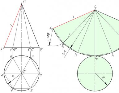
In the figure below, a regular hexagonal pyramid SABCDEF is inscribed in a right circular cone, and the approximate development of its lateral surface consists of six isosceles triangles - the faces of the pyramid.

Consider the triangle S 0 A 0 B 0 . The lengths of its sides S 0 A 0 and S 0 B 0 are equal to the generatrix l of the conical surface. The value A 0 B 0 corresponds to the length A’B’. To construct a triangle S 0 A 0 B 0 in an arbitrary place in the drawing, lay off the segment S 0 A 0 =l, after which from points S 0 and A 0 we draw circles with radius S 0 B 0 =l and A 0 B 0 = A'B' respectively. We connect the intersection point of circles B 0 with points A 0 and S 0.
We construct the faces S 0 B 0 C 0 , S 0 C 0 D 0 , S 0 D 0 E 0 , S 0 E 0 F 0 , S 0 F 0 A 0 of the pyramid SABCDEF similarly to the triangle S 0 A 0 B 0 .
Points A, B, C, D, E and F, lying at the base of the cone, are connected by a smooth curve - an arc of a circle, the radius of which is equal to l.
Inclined cone development
Let us consider the procedure for constructing a scan of the lateral surface of an inclined cone using the approximation (approximation) method.

Algorithm
- We inscribe the hexagon 123456 into the circle of the base of the cone. We connect points 1, 2, 3, 4, 5 and 6 with the vertex S. The pyramid S123456, constructed in this way, with a certain degree of approximation is a replacement for the conical surface and is used as such in further constructions.
- We determine the natural values of the edges of the pyramid using the method of rotation around the projecting line: in the example, the i axis is used, perpendicular to the horizontal projection plane and passing through the vertex S.
Thus, as a result of the rotation of edge S5, its new horizontal projection S’5’ 1 takes a position in which it is parallel to the frontal plane π 2. Accordingly, S’’5’’ 1 is the actual size of S5. - We construct a scan of the lateral surface of the pyramid S123456, consisting of six triangles: S 0 1 0 6 0 , S 0 6 0 5 0 , S 0 5 0 4 0 , S 0 4 0 3 0 , S 0 3 0 2 0 , S 0 2 0 1 0 . The construction of each triangle is carried out on three sides. For example, △S 0 1 0 6 0 has length S 0 1 0 =S’’1’’ 0 , S 0 6 0 =S’’6’’ 1 , 1 0 6 0 =1’6’.
The degree to which the approximate development corresponds to the actual one depends on the number of faces of the inscribed pyramid. The number of faces is chosen based on the ease of reading the drawing, the requirements for its accuracy, the presence of characteristic points and lines that need to be transferred to the development.
Transferring a line from the surface of a cone to a development
Line n lying on the surface of the cone is formed as a result of its intersection with a certain plane (figure below). Let's consider the algorithm for constructing line n on a scan.

Algorithm
- We find the projections of points A, B and C at which line n intersects the edges of the pyramid S123456 inscribed in the cone.
- We determine the natural size of the segments SA, SB, SC by rotating around the projecting straight line. In the example under consideration, SA=S’’A’’, SB=S’’B’’ 1 , SC=S’’C’’ 1 .
- We find the position of points A 0 , B 0 , C 0 on the corresponding edges of the pyramid, plotting on the scan the segments S 0 A 0 =S''A'', S 0 B 0 =S''B'' 1, S 0 C 0 =S''C'' 1 .
- We connect points A 0 , B 0 , C 0 with a smooth line.
Development of a truncated cone
The method described below for constructing the development of a right circular truncated cone is based on the principle of similarity.

Purpose of the lecture:studying the properties of development and methods for constructing developments of polyhedra and surfaces of revolution
· Development of surfaces. General concepts.
· Methods for constructing developments: triangulation, normal section and rolling methods.
· Construction of developments of faceted surfaces and surfaces of revolution.
Development of surfaces. General concepts
| Scan | a flat figure obtained by combining the surface of a geometric body with a plane (without superimposing faces or other surface elements on top of each other). The development can be considered as a flexible, inextensible film. Some of the surfaces presented in this way can be combined with a plane by bending. Moreover, if a surface compartment can be combined with a plane without tearing or gluing, then such a surface is called unfolding, and the resulting flat figure is its sweep. |
| Basic sweep properties | 1 The lengths of the two corresponding lines of the surface and its development are equal to each other; 2 The angle between the lines on the surface is equal to the angle between their corresponding lines on the development; 3 A straight line on the surface also corresponds to a straight line on the development; 4 Parallel lines on the surface also correspond to parallel lines on the development; 5 If a line belonging to a surface and connecting two points on the surface corresponds to a straight line on a development, then this line is a geodesic. |
Methods of triangulation, normal section and rolling
Construction of developments of faceted surfaces and surfaces of revolution
a) Development of the surface of a polyhedron.
The development of a polyhedral surface is a flat figure obtained by sequentially combining all the faces of the surface with the plane.
Since all the faces of a polyhedral surface are depicted on a development in full size, its construction comes down to determining the size of individual faces of the surface - flat polygons.
Triangulation method
Example 1. Pyramid development (Figure 13.1).
When constructing the development of a pyramid, the triangle method is used. The development of the side surface of the pyramid is a flat figure consisting of triangles - the faces of the pyramid and a polygon - the base. Therefore, constructing the development of a pyramid comes down to determining the natural size of the base and faces of the pyramid. The faces of the pyramid can be constructed using the three sides of the triangles that form them.
Figure 13.1. The pyramid and its development
To do this, you need to know the actual size of the ribs and sides of the base. The construction algorithm can be formulated as follows (Figure 13.2):

Figure 13.2. Determination of true value
base and edges of the pyramid
The points located inside the scan contour are found in one-to-one correspondence with the points of the surface of the polyhedron. But for each point of the edges along which the polyhedron is cut, there correspond on the development two points belonging to the contour of the development. An example of the first point in the figures is the point TO 0 And TO Î SAD , and the second case is illustrated by the points M 0 And M 0 * . To determine a point TO 0 on the development it was necessary to find the lengths of the segments using its orthogonal projections AM (method of replacing projection planes) and SK (rotation method). These segments were then used to construct, first, a straight line on the development S 0 M 0 and finally the points TO 0 .

Figure 13.3. Constructing a pyramid sweep
Normal section method
In general, a prism is scanned as follows. Transform the diagram so that the edges of the prism become parallel to the new projection plane. Then the ribs are projected onto this plane in natural size.
Example 2. Prism development (Figure 13.4).
Intersecting a prism with an auxiliary plane α , perpendicular to its lateral edges (normal section method), construct projections of a figure of normal section - a triangle 1 , 2 , 3 , and then determine the true value of this section. In the example, it was found by the rotation method.
Next we construct a segment 1 0 -1 0 * , equal to the perimeter of the normal section. Through dots 1 0 , 2 0 , 3 0 And 1 0 * draw straight lines perpendicular 1 0 -1 0 * , on which the corresponding sections of the lateral edges of the prism are laid, taking them from the new frontal projection. So, on the perpendicular passing through the point 1 0 , segments are postponed 1 0 D 0 =1 4 D 4 And 1 0 A 0 =1 4 A 4 .. By connecting the ends of the postponed segments, a development of the lateral surface of the prism is obtained. Then the base is completed.
Rolling method
Example 3. Development of a prism, a special case when the base of the prism is projected in full size onto one of the projection planes (Figure 13.5).
The development of the side surface of such a prism is carried out by rolling out. This method is as follows. First, as in the previous example, the diagrams are transformed so that the side edges of the prism become parallel to one of the projection planes.

Figure 13.4. Development of a prism using the normal section method

Figure 13.5. Prism development using the rolling method
The new prism projection is then rotated around the edge WITH 4 F 4 until the edge ACDF will not become parallel to the plane P 4 .
In this case, the position of the rib WITH 4 F 4 remains unchanged, and the points belonging to the edge AD move along circles, the radius of which is determined by the natural size of the segments A.C. And DF (since the bases of the prism are parallel P 1 then they are projected onto this projection plane without distortion, i.e. R=A 1 C 1 =D 1 F 1 ), located in planes perpendicular to the edge WITH 4 F 4 .
Thus, the trajectories of the points A And D to the plane P 4 projected into straight lines perpendicular to the edge WITH 4 F 4 .
When the edge ACDF will become parallel to the plane P 4 , it is projected onto it without distortion i.e. peaks A And D will be far from the fixed vertices C And F at a distance equal to the natural size of the segments A.C. And DF . Thus, by noting the perpendiculars along which the points move A 4 And D 4 arc of radius R=A 1 C 1 =D 1 F 1 , you can get the desired position of the scan points A 0 And D 0 .
Next edge ABDE rotate around the edge AD . On perpendiculars along which points move B 4 And E 4 make serifs from dots A 0 And D0 arc of radius R=A 1 B 1 =D 1 E 1 . The development of the last side face of the prism is constructed in a similar way.
The process of sequentially finding the faces of a prism by rotating around the edges can be represented as rolling out a prism onto a parallel plane P 4 and passing through the rib WITH 4 F 4 .
Constructing a point on a sweep TO , belonging to the side face ABDE, clear from the picture. Previously, a straight line was drawn through this point along the edge NM , parallel to the side edges, which is then built on the development.
b) Development of a cylindrical surface.
The development of a cylindrical surface is carried out similarly to the development of a prism. An n-gonal prism is first inserted into a given cylinder (Figure 13.6). The more angles in the prism, the more accurate the scan (with n → the prism is converted into a cylinder).
V ) Development of a conical surface
The development of a conical surface is carried out similarly to the development of a pyramid, having previously inscribed an n-gonal pyramid into the cone (Figure 13.6).
If the surface of a straight cone is given, then the development of its lateral surface represents a circular sector, the radius of which is equal to the length of the generatrix of the conical surface l , and the central angle φ =360 o r/l , Where r – radius of the circle of the base of the cone.

Figure 13.6. Development of a cylindrical surface

Figure 13.7. Development of a conical surface
Control questions
1 What is a surface development called?
2 Which surfaces are called developable and which are called non-developable?
3 Specify the basic properties of sweeps
4 Indicate the sequence of graphic constructions of developments of the surfaces of a cone and cylinder.
5 What methods of constructing developments of polyhedra do you know?
Surface development is a flat figure formed by consistent alignment of a surface with a plane without breaks or folds. When unfolded, the surface is treated as flat but inextensible. The purpose of surface development is to create models of surfaces from sheet material by subsequent bending and “folding” of their developments.
Basic properties of sweeps:
The straight line on the surface turns into a straight line on the development;
Parallel lines on the surface transform into parallel lines on the development;
The lengths of a line segment on the surface and the same line on a development are equal;
The angles between the lines on the surface and between the corresponding lines on the development are equal;
The development area is equal to the surface area;
All sizes on the scanner are actual size.
All surfaces are divided into developable and non-developable.
Developable surfaces include:
Faceted surfaces (pyramids, prisms, etc.), because the flat elements of the polyhedron are precisely aligned with the scan plane. In this case, the scan is called accurate.
Ruled surfaces (cylindrical, conical and surfaces with a return edge), i.e. These are surfaces in which adjacent straight lines are parallel or intersect.
Non-developable surfaces include all other ruled surfaces, as well as non-ruled surfaces (cylindroids, conoids, spheres). Developments of these surfaces in this case are called approximate or conditional.
1.5.1 Development of surfaces of polyhedra
When constructing nets of polyhedra, the actual size of all its faces (flat polygons) is determined. In this case, various methods of converting the drawing are used. The choice of one or another method depends on the type of polyhedron and its location relative to the projection planes.
1.5.1.1 Prism surface development
There are two ways to develop a prism: the “normal section” method and the “rolling” method.
“Normal section” method used to develop the surface of prisms in general position. In this case, a normal section of the prism is constructed (i.e., a plane located perpendicular to the lateral edges of the prism is introduced) and the natural dimensions of the sides of the polygon of this normal section are determined.
We will consider an example of performing the development of a trihedral prism of general position using the “normal section” method in the problem according to Figure 1.5.1
Let us pay attention to the fact that in our case the lateral edges of the prism are frontal, i.e. to the plane P 2 they are projected life-size.
1) In the frontal projection plane, we construct a frontally projecting plane γ(γ 1 ) , which is simultaneously perpendicular to the lateral edges of the prism AD, CF, BE. The resulting normal section will be expressed in the form of a triangle 123 . Using the method of plane-parallel movement, we determine its natural size in accordance with Figure 1.5.2.
2) Let us plot all sides of the normal section successively on a straight line: 1 0 2 0 =1 1 1 2 1 1 ; 2 0 3 0 =2 1 1 3 1 1 ; 3 0 1 0 =3 1 1 1 1 1 .
3) Through points 1 0 ,2 0 ,3 0 draw lines perpendicular to the line 1 0 -1 0 and put on them the actual size of the side ribs: 1 0 D 0 =1 2 D 2 And 1 0 A 0 = 1 2 A 2 ; 2 0 F 0 = 2 2 F 2 And 2 0 C 0 = 2 2 C 2 ; 3 0 E 0 = 3 2 E 2 And 3 0 B 0 = 3 2 B 2 .
4) Connect the resulting points of the upper and lower bases of the prism with straight lines A 0 B 0 C 0 And D 0 F 0 E 0 . Flat figure A 0 B 0 C 0 D 0 F 0 E 0 is the desired development of the lateral surface of this prism. To construct a complete development, it is necessary to attach the natural values of the bases to the development of the lateral surface. To do this, we will use the natural values of their sides obtained on the scan A 0 C 0 , C 0 B 0 , B 0 A 0 And D 0 F 0 , F 0 E 0 , E 0 D 0 in accordance with Figure 1.5.3
Figure 1.5.1

Figure 1.5.2

Figure 1.5.3 – Development of a prism using the “normal section” method
The "rolling out" method. This method is convenient for constructing developments of prisms with a base lying in the plane of the level. The essence of the method is to sequentially align the side faces with the drawing plane by rotating them around the corresponding edges of the prism (Figure 1.5.4).
Using this method, a development of the surface of the prism is constructed. ABCDEF, the side edges of which are frontal, and the lower base lies in the horizontal plane (Figure 1.5.5).
1) The lateral faces of the prism are compatible with the frontal plane passing through the rib AD. This is convenient in this case, because frontal projections of the lateral edges of the prism are equal to their true length. Then the edge A 0 D 0 the scan will coincide with the frontal projection of the rib AD(A 2 D 2 ) .
2) To determine the true size of the side face on the scan ADEB rotate it around the edge AD to a position parallel to the frontal plane of projections. To determine the position of a point on a sweep B 0 , from point B 2 restore the perpendicular to A 2 D 2 . Dot B 0 will be found at the intersection of this perpendicular with a circular arc of radius R 1 , equal to the true size of the edge AB and drawn from the point A 2 as if from the center.
3) Point E 0 will be determined on the scan as the result of the intersection of the line B 0 E 0 parallel frontal projection of the rib BE(B 2 E 2 ), and the perpendicular restored from the point E 2 To A 2 D 2 .
4) Points C 0 And A 0 constructed similarly to a point B 0 at the intersection of perpendiculars from points C 2 And A 2 to the frontal projections of the ribs, with arcs of circles drawn from the points B 0 And C 0 as from centers with radii R 2 And R 3 , equal respectively to the edges B.C. And C.A.. Points F 0 And D 0 are defined similarly to the point E 0 .
5) By connecting successively combined vertices with broken lines, we obtain a scan of the lateral surface of the prism A 0 B 0 C 0 A 0 D 0 F 0 E 0 D 0 . If necessary, you can obtain a full development of the prism by attaching to it the natural values of both bases.
If the lateral edges of the prism occupy a general position, then by preliminary transformation of the drawing they must be brought to the position of the level lines.
3.86 /5 (77.14%) 7 votes
Cone development. Constructing a cone scan.
Calculation of cone development.
Let's take the vertical and horizontal projections of the cone (Fig. 1, a). The vertical projection of the cone will have the form of a triangle, the base of which is equal to the diameter of the circle, and the sides are equal to the generatrix of the cone. The horizontal projection of the cone will be represented by a circle. If the height of the cone H is given, then the length of the generatrix is determined by the formula:
i.e., like the hypotenuse of a right triangle.
Wrap the cardboard around the surface of the cone. By unfolding the cardboard again into one plane (Fig. 1, b), we obtain a sector whose radius is equal to the length of the generatrix of the cone, and the length of the arc is equal to the circumference of the base of the cone. A complete development of the side surface of the cone is performed as follows.

Rice. 1. Cone development:
a - projection; b - scan.
Cone sweep angle.
Taking the generatrix of the cone as the radius (Fig. 1, b), an arc is drawn on the metal, on which a segment of the arc is then laid KM , equal to the circumference of the base of the cone 2 π r. Arc length in 2 π r corresponds to the angle α , the value of which is determined by the formula:
r is the radius of the circle of the base of the cone;
l is the length of the cone generatrix.
The construction of the sweep comes down to the following. Not part of the arc is deposited along the length of the previously drawn arc KM , which is practically impossible, and the chord connecting the ends of this arc and corresponding to the angle α . The magnitude of the chord for a given angle is found in the reference book or indicated on the drawing.
Found points KM connect to the center of the circle. The circular sector obtained as a result of the construction will be the unfolded lateral surface of the cone.